


32
307–758
DRIVE
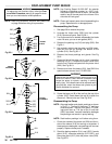
HOUSING, CONNECTING ROD & CRANKSHAFT REPLACEMENT
WARNING
To
reduce the risk of serious injury
, follow the illus
-
trated Pressure Relief Procedure warning on
page 24 whenever you are instructed to relieve
pressure.
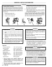
NOTE: Read the GENERAL REPAIR INFORMATION
on
page 24 before doing this procedure.
NOTE:
Stop the sprayer at the bottom of its stroke to
get the crankshaft (69) in its lowest position.
T
o lower the crankshaft manually
, carefully ro
-
tate the blades of the motor fan with a screw
-
driver.
NOTE:
Refer to Fig 26 unless otherwise noted.
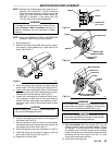
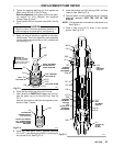
1.
Remove the front cover
.
2.
Hold
a wrench
on the pump intake valve and unscrew
the
suction tube.
3.
Disconnect the hose (68) from the pump.
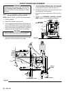
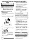
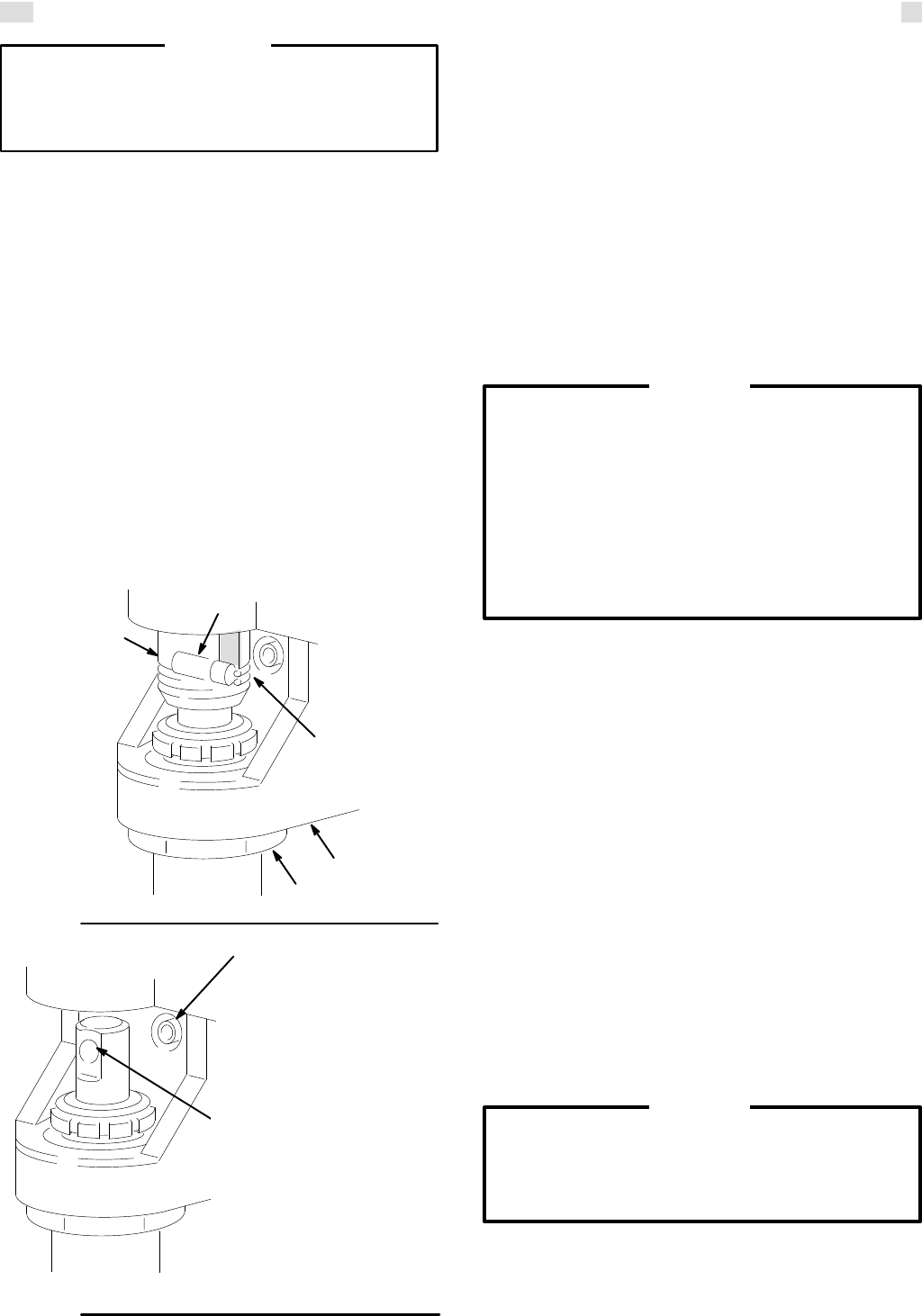
4.
Use a screwdriver to push up the retaining spring
(42).
Push the pin (43) out the rear
. See Fig 32–1.
42
70
43
73
41
25,18
Fig 32–1
Fig 32–1
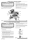
Turn
the displacement
rod
so the pin hole faces
straight
back.
Insert a hex
key wrench through the
hole
to unscrew the
screw
(25).
01579
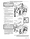
5.
Loosen the jam nut (41) with an adjustable wrench.
Unscrew
and remove the pump.
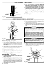
6. See
Fig
32–1 to remove one of the screws (25) which
is hidden.
Remove the other two screws (25) from
the
recess of the drive housing. See Fig 26.
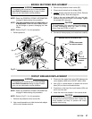
7.
Remove the motor shield (58).
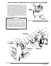
8. Remove
the two screws (14) holding the motor
(75)
to
the drive housing (73).
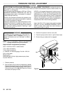
9.
Lightly tap the lower rear of the drive housing (73)
with
a plastic mallet to loosen it from the front of the
motor.
Then pull the drive housing straight of
f.
Do
not allow the gear (71) to fall. It may stay attached
to
the drive housing or to the motor
.
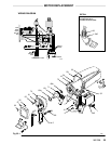
Do
not lose the thrust
balls (8) located at each end of
the gear (71). The balls are heavily covered with
grease and usually stay in the shaft recesses, but
they
could be dislodged. If caught between the gears
and not removed, the balls will damage the drive
housing.
If the balls are not in place, the bearings will
wear
prematurely
.
CAUTION
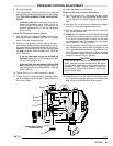
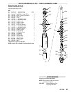
10.
Inspect the drive housing (73) for excessive wear
and
replace parts as needed.
11. Pull the crankshaft (69) out. Inspect it for wear or
damage and replace it, if necessary. Be sure the
thrust
bearings (69a and 69b) are in
the proper place
on
crankshaft.
12. Remove
the connecting rod (70). Inspect it for
wear
or
damage. Replace the rod, if necessary
.
13. Evenly lubricate the inside of the bronze bearing in
the
drive housing with high quality motor oil. Liberally
pack the roller bearing and gears with bearing
grease.
14. Carefully
align the drive housing and front of the mo
-
tor
with the locating pins.
Push the drive housing onto
the motor, or tap it into place with a plastic
mallet.
DO
NOT use the drive housing screws (25) to try
to
align
or seat the housing to the motor;
doing so will
not ensure proper alignment, but will cause prema
-
ture bearing wear
.
CAUTION
15. Install
the
screws (14 and 25) and lockwashers (18)
on
the drive housing and tighten evenly
.
16.
Reinstall the motor shield (58).