


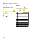

Motor Control Diagnostic Codes
14 312066Z
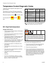
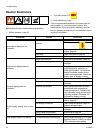
E25: High line voltage
Supply voltage too high. Check Reactor voltage require-
ments, page 73.
E26: Low line voltage
Supply voltage too low. Check Reactor voltage require-
ments, page 73.
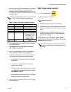
E27: High Motor Temperature
1. Motor temperature too high. Reduce pressure, gun
tip size, or move Reactor to a cooler location. Allow
one hour for cooling.
2. Check fan operation.
3. Ensure there is no obstruction around the fan area
that would cause lack of airflow; ensure the
motor/fan shroud is installed.
4. Ensure the unit is being operated with the front
cover on.
5. Ensure the brush wear/over temp switch wire
assembly is plugged into J7 (E-20/E-XP1) or J6
(E-30/E-XP2) of the motor control board.
6. With the main power off, unplug the wire harness
from J7 (E-20/E-XP1) or J6 (E-30/E-XP2) on the
motor control board and install a jumper wire on
pins 1 and 2. Turn the main power back on.
If E27 is gone:
If the E27 error is gone and the motor is truly not over-
heated, then the problem can be in the motor/motor wire
harness assembly. Measure the resistance between the
two yellow wires that go to pins 1 and 2 of the motor
connector. If there is an open connection, the thermal
overload switch is open or there is a broken wire inside
the motor, or a broken wire in the motor harness.
If the E27 error code is still there, double check if pins 1
and 2 are jumpered properly. If jumpered properly, then
it would appear that the problem is with in the motor
control board.
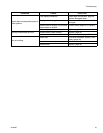
E28: High current in motor
Check motor control board:
1. Turn the master power off.
2. Disconnect socket J4 (E-20/E-XP1) J1
(E-30/E-XP2) on the motor control board.
3. Turn the master power back on.
4. If the E28 error did not go away then there is a prob-
lem with the motor control board. Replace board,
page 34.
Check motor:
1. Check to see if the motor rotates freely.
2. Check to see if the brushes are damaged.
3. Check that the voltage going to the motor is good.
4. Check the three wire (yellow, yellow, orange) motor
connector to the motor board. A gentle tug on each
wire individually at the connector should identify the
loose wire. If a wire pulls out, bend the locking tab
on the crimp end, insert the wire until it seats and
repeat gentle tug.
5. If the above does not resolve the problem, replace
the motor, page 33.
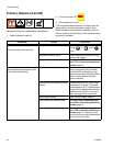
E29: Brush Wear
1. Check for normal brush wear, which causes the
brush sensor to come in contact with the motor
commutator. Replace the brushes, page 30.
2. Check spade plug. The spade plug inside the motor
housing may be twisted and contacting the commu-
tator side of the brush sensor assembly, causing a
false alarm. Follow the orange wire coming from J7
(E-20/E-XP1), or J6 (E-30/E-XP2), up to the spade
connector on the motor. Using a flashlight, ensure
the spade plug assembly is not making contact with
the metal housing of the brush assembly.
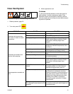
CAUTION
Prolonged operation of motor after a brush wear
warning may result in failure of motor and motor con-
trol board.