


Repair
312066Z 37
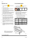
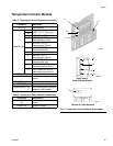
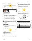
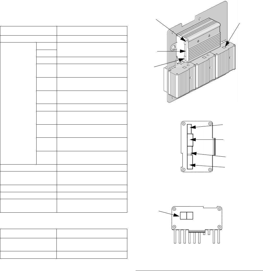
Temperature Control Module
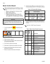
Table 6: Temperature Power Module Connections
Table 5: Temperature Control Module Connections
Connector Description
DATA (A) Data reporting
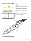
SENSOR (B)
PIN
HOSE T/C P; FTS (purple)
12
11 HOSE T/C R; FTS (red)
10 HOSE T/C S; FTS (silver
(unshielded bare wire))
9 HEATER T/C B, Y;
Thermocouple (yellow)
8 HEATER T/C B, R;
Thermocouple (red)
7 Not used
6 HEATER T/C A, Y;
Thermocouple (yellow)
5 HEATER T/C A, R;
Thermocouple (red)
4, 3 OVERTEMPERATURE B;
Overtemperature switch B
2, 1 OVERTEMPERATURE A;
Overtemperature switch A
DISPLAY (C) Display
COMMUNICATION (D) Communication to power
boards
PROGRAM (E) Software programming
BOOT (F) Software bootloader
POWER/RELAY (G) Circuit board power input and
contactor control output
Connector Description
COMMUNICATION
(H)
Communication to control
board
POWER (J) Power to heater
F
IG
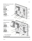
. 5: Temperature Control Module Connections
A
B
C
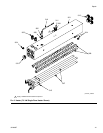
Bottom of Power Modules
Right Side of
Control Heater Module
D
E
F
G
ti9875a
ti9843a1
ti9843a4
H
J