


Repair
36 312066Z
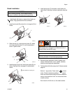
Transducers
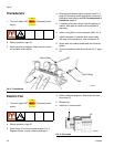
1. Turn main power OFF . Disconnect power
supply.
2. Relieve pressure, page 23.
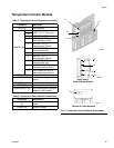
3. Refer to electrical diagrams. Motor control board is
on right side inside cabinet.
4. Disconnect transducer cables at board; see F
IG
. 2,
page 35. Reverse A and B connections and check if
diagnostic code follows; see E21: No component A
transducer, page 12.
5. If transducer fails test, thread cable through top of
cabinet. Note path as cable must be replaced in
same way.
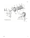
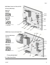
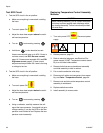
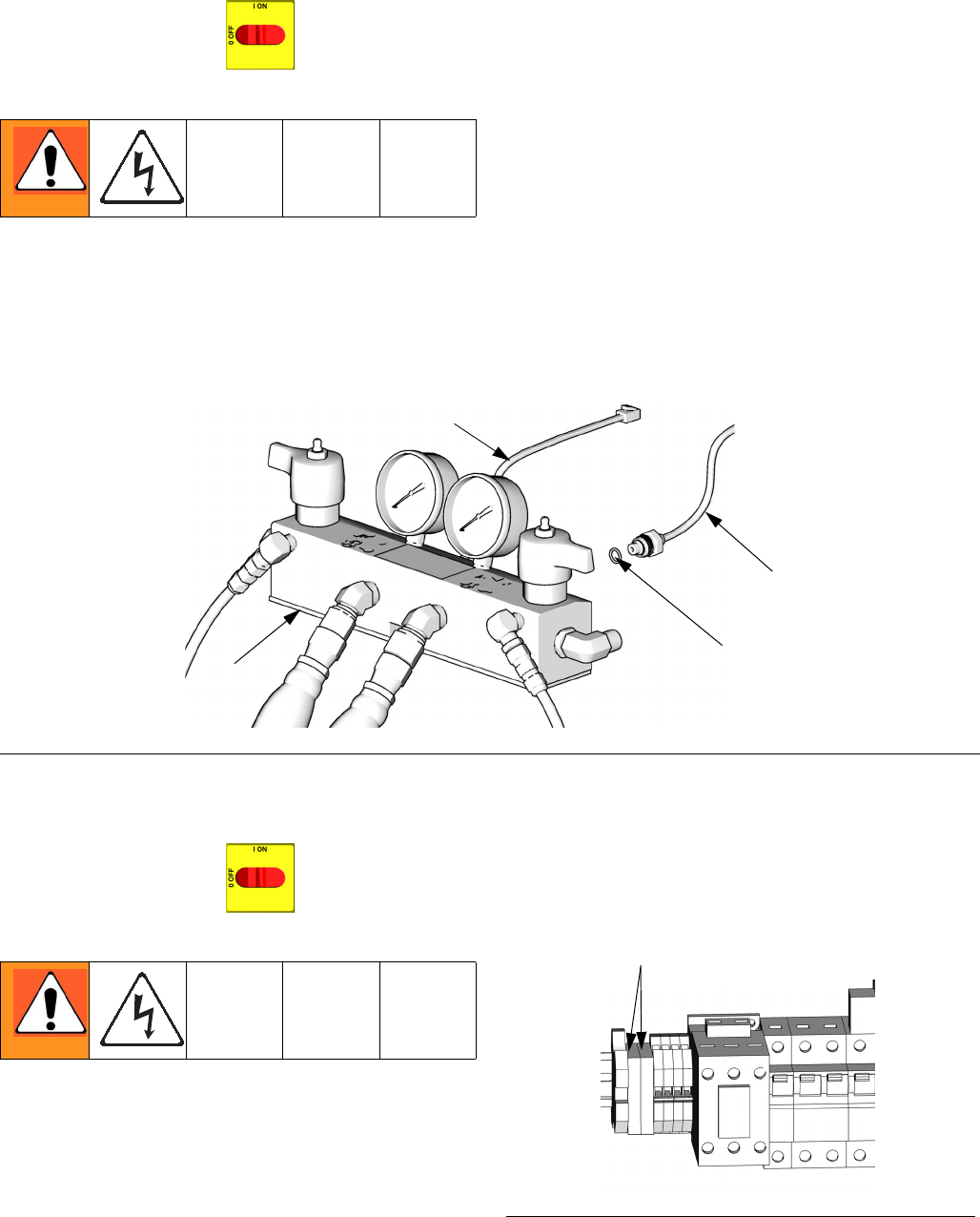
6. Install o-ring (820) on new transducer (806), F
IG
. 3.
7. Install transducer in manifold. Mark end of cable
with tape (red=transducer A, blue=transducer B).
8. Route cable into cabinet and thread into bundle as
before.
9. Connect transducer cable at board; see F
IG
. 2, page
35.
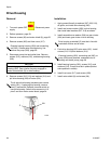
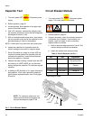
Electric Fan
1. Turn main power OFF . Disconnect power
supply.
2. Relieve pressure, page 23.
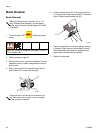
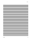
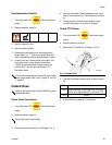
3. Check fuses (F) at left of breaker module, F
IG
. 4.
Replace if blown. If good, continue with step 4.
4. Refer to electrical diagrams. Disconnect fan wires
from fuses (F).
5. Remove fan.
6. Install fan in reverse order.
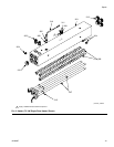
F
IG
. 3. Transducers
TI10957a
820
806 (B Side)
801
806 (A Side)
F
IG
. 4. Fan Fuses
F
ti9884a-1