


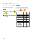
Motor Control Diagnostic Codes
312066Z 15
3. Check wiring. The orange brush sensor wire coming
out of the brush may be routed online with the com-
mutator wiring (thick red wire), causing a false
alarm. Reroute the orange wire coming out of the
brush, away from the commutator wiring.
4. Check motor control board.
• Remove the plug in J7 (E-20/E-XP1), or J6
(E-30/E-XP2). (This will cause an E27 alarm).
• To remove the E27 alarm, use a jumper wire on the
motor control board, across the two pins that the
two yellow wires plug into. Then turn the unit on.
• The E27 as well as the E29 alarm should be gone. If
the E27 alarm is not gone double-check your
jumper.
• If the jumper is installed correctly and the E29 alarm
is still there, replace the motor control board, page
34.
E31: Motor Control Failure
(E-30 and E-XP2 only)
The E31 error code represents a motor drive error. This
indicates that the 24G881 motor control board has mal-
functioned and needs to be replaced. A motor control
board failure may also be indicated by the motor starting
up immediately upon the application of power to the sys-
tem, without pressing . This is an indication that
the output drivers of the motor control have shorted out
and are delivering full power to the motor at all times.
The cause of the failure may be one of the following con-
ditions: motor failure, capacitor failure, shorted or frayed
wiring, or inadequate power supply. Perform the follow-
ing procedure before replacing the motor control board.
1. Turn main power OFF . Disconnect power
supply.
2. Relieve pressure, page 23.
3. Perform the following inspections.
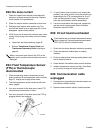
a. Motor failure: Inspect the motor commutator by
removing the top brush (see Brush Removal,
page 30). Rotate the motor, inspecting the
whole commutator for burns, pocking, or shorts
between poles. Continue rotating the motor for a
complete pump cycle, up and down, to ensure
that there is no mechanical interference or
restriction in the pump lower or gear drive sys-
tem.
b. Capacitor failure: Inspect and test the motor
start capacitor, following the Capacitor Test
instructions on page 32.
c. Shorted or frayed wiring: Inspect all wiring
connected to the motor control board and the
motor, for shorts or frayed insulation. Replace
any compromised wires with wire of the same
gauge, color. and temperature rating.
d. Inadequate power supply: Verify that the
power source is of the correct voltage and cur-
rent rating for the system, and that all phases
are properly connected. Ensure that the power
does not dip or surge during operation.
Prior to shutting down the generator, ensure
that the motor has stopped and the main dis-
connect is opened. If the generator is stopped
during operation, even due to running out of
fuel, the drop in supply voltage may cause a
motor drive failure.
Wait 5 minutes for stored voltage to discharge (E-30
and E-XP2 models only).