


Repair
34 312066Z
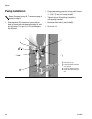
Motor Control Board
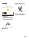
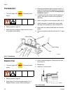
1. Turn main power OFF . Disconnect power
supply.
2. Relieve pressure, page 23.
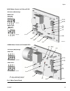
3. Refer to electrical diagrams. Motor control board is
on right side inside cabinet.
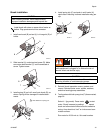
4. Put on static conductive wrist strap.
5. Disconnect all cables and connectors from board.
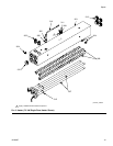
6. Remove nuts (40) and take entire motor control
assembly to workbench.
7. Remove screws and take board off heatsink.
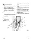
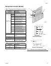
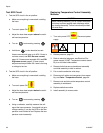
8. Set DIP switch (SW2) on new board. See T
ABLE
3
for factory settings. See F
IG
. 2 for location on board.
9. Install new board in reverse order. Apply thermal
heatsink compound to mating surfaces of board and
heatsink.
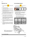
Motor control board has one red LED (D11). Power
must be on to check. See F
IG
. 2 for location. Func-
tion is:
• Startup: 1 blink for 60 Hz, 2 blinks for 50 Hz.
• Motor running: LED on.
• Motor not running: LED off.
• Diagnostic code (motor not running): LED
blinks diagnostic code, pauses, then repeats
(for example, E21=21 blinks, pause, 21 blinks).
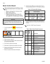
CAUTION
Before handling board, put on a static conductive wrist
strap to protect against static discharge which can
damage board. Follow instructions provided with wrist
strap.
Wait 5 minutes for stored voltage to discharge (E-30
and E-XP2 models only).
Table 3: DIP Switch (SW2) Settings
DIP
Switch Switch Position
Switch 1 not used
Switch 2 ON for E-20 and
E-30 models
OFF for E-XP1 and
E-XP2
Switch 3 ON to enable pres-
sure imbalance
warning
OFF to enable
pressure imbalance
alarm
Switch 4 not used
Order Part 110009 Thermal Compound.
Table 4: Motor Control Board Connectors
Model
E-20
and
E-XP1
Model
E-30
and
E-XP2 Pin Description
J1 N, L n/a Main motor power
J8 J3 n/a Transducer B
J4 J1 n/a Motor output
J7 J6 1, 2 Motor thermal overload signal
3 Brush wear signal
J3 J5 n/a Transducer A
J10 J7 1-4 Not used
5, 6 Cycle switch signal
7-10 Jumper 15C866 (available in
repair kit 246961)
J12 J12 n/a Data reporting
J13 J13 n/a To display board