


Repair
312066Z 43
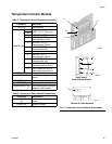
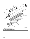
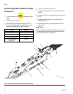
Overtemperature Switch
1. Turn main power OFF . Disconnect power
supply.
2. Relieve pressure, page 23.
3. Wait for heaters to cool.
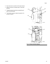
4. Remove heater shroud.
5. Disconnect one leadwire from overtemperature
switch (308), F
IG
. 7. Test across switch with ohm-
meter. Resistance must be approximately 0 ohms.
6. If switch fails test, remove wires and screws. Dis-
card failed switch. Apply thermal compound
110009, install new switch in same location on
housing (301), and secure with screws (311).
Reconnect wires.
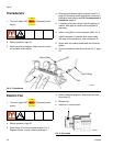
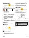
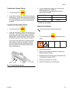
Heated Hose
Check Hose Connectors
1. Turn main power OFF . Disconnect power
supply.
2. Relieve pressure, page 23.
3. Disconnect hose connector (D) at Reactor, F
IG
. 8.
4. Using an ohmmeter, check between the two termi-
nals of the connector (D). There should be continu-
ity.
5. If hose fails test, retest at each length of hose,
including whip hose, until failure is isolated.
Check FTS Cables
1. Turn main power OFF . Disconnect power
supply.
2. Relieve pressure, page 23.
3. Disconnect FTS cable (F) at Reactor, F
IG
. 8.
4. Test with ohmmeter between pins of cable connec-
tor.
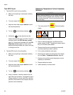
5. If cable fails test, retest at FTS, page 44.
If wires need replacement, disconnect from temper-
ature control board. See T
ABLE
5, page 37 and F
IG
.
5, page 37.
Refer to the heated hose manual 309572 for hose
replacement parts.
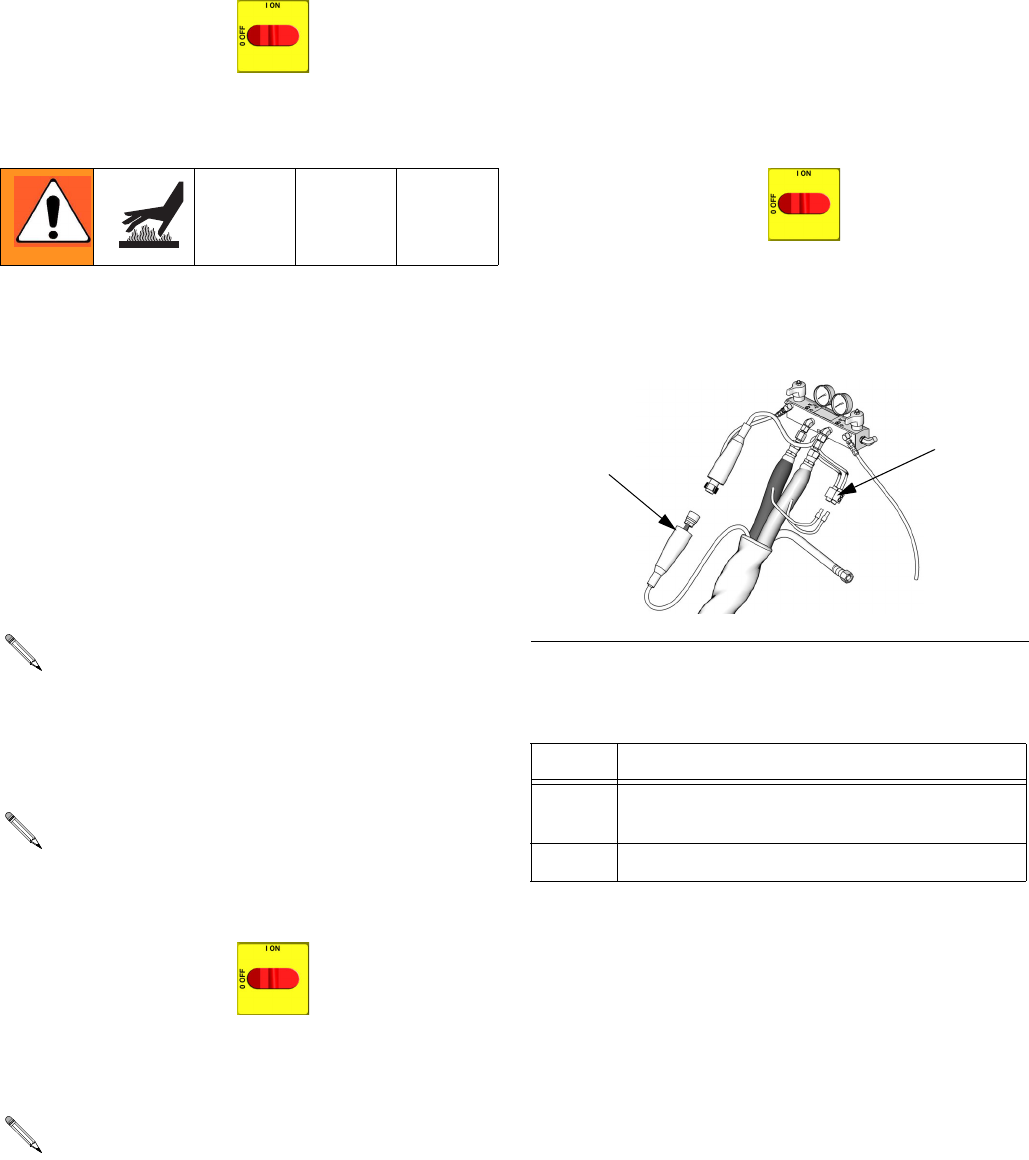
Whip hose must be connected.
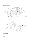
F
IG
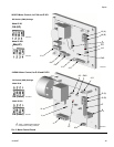
. 8. Heated Hose
Pins Result
1 to 2 approximately 35 ohms per 50 ft (15.2 m) of
hose, plus approximately 10 ohms for FTS
1 to 3 infinity
TI10964a
F
D