


Setup
20 3A0420T
Motor Position
The motor position must be set for the volume mix ratio
of the system.
NOTE: Changing the motor position does not change
the mix ratio.
Check Motor Position
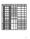
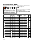
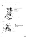
1. Verify that the correct pumps are mounted for your
mix ratio by volume. See chart in Bare Proportion-
ing Pump Packages on page 13.
2. Verify that the motor position is adjusted correctly
for that mix ratio. See F
IG
. 6. If not, perform the fol-
lowing Change Motor Position procedure.
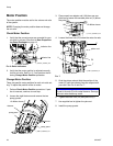
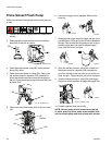
Change Motor Position
There are specific motor positions for each mix ratio set-
ting. To adjust the position of the air motor:
1. Perform Check Motor Position procedure. If posi-
tion is incorrect, continue to next step.
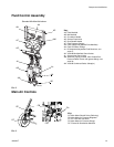
2. Loosen the eight fasteners and remove the two
pump guards.
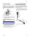
3. Place wrench on adapter rod (104) then use sup-
plied tool to loosen the serrated yoke nut (V) above
the yoke (T).
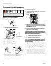
4. Loosen the three nuts (P2) below the motor tie rods.
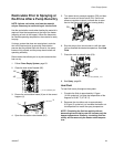
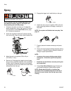
5. Grab the piston rod and slide the position of the
motor (E) until the indicator lines are aligned with
your ratio. See F
IG
. 6 and F
IG
. 7.
6. Tighten the three nuts (P2) and yoke nut (V).
7. Use supplied tool to tighten the yoke nut.
8. Install the pump guards.
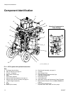
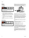
F
IG
. 6: Ratio indicators
indicator line
indicator line
r_258914_3a0420a_10b
Air Motor shown
pump guard
pump guard
fastener
fastener
r_258914_3a0420a_4a-1
Air Motor shown
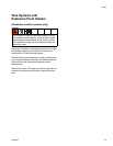
F
IG
. 7
NOTICE
Do not hit tie rods (P) with a steel hammer. Damage
to the air motor base may result.
T
V
r_571101_3a0420a_2a-2
104
Air Motor shown
T
E
piston rod
P2
V
r_258914_3a0420a_5a
Air Motor shown