


Repair
38 3A0420T
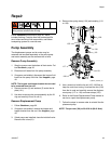
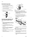
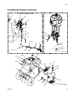
Mix Manifold Assembly
1. Follow Pressure Relief Procedure, page 22.
2. Disconnect the fluid hose (25) and the flush hose
from the mix manifold (36).
3. Loosen the union fittings (306) that connect to the
mix manifold adapter fittings.
4. Remove the mix manifold assembly (36).
5. See mix manifold manual for service and repair
instructions.
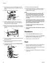
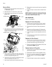
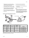
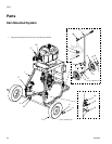
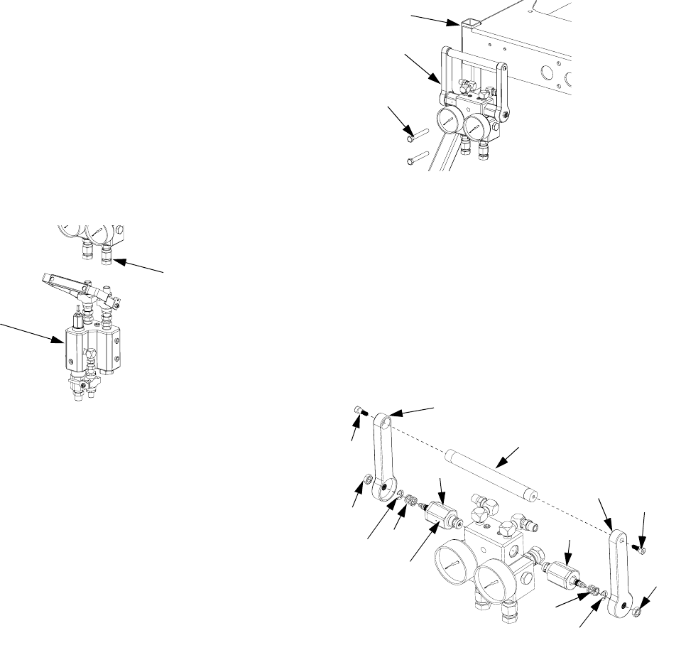
Fluid Circulation Manifold with
Over Pressure Relief Valves
See F
IG
. 11.
1. Flush before repairing equipment, if possible. See
Empty and Flush Entire System (new system or
end of job), page 29.
2. Follow Pressure Relief Procedure, page 22.
3. Disconnect all fluid hoses from the fluid circulation
manifold (35).
4. Remove the mix manifold if it is assembled to the
fluid circulation manifold. See Mix Manifold
Assembly for instructions.
5. Loosen the two screws (37) that secure the manifold
(35) to the cart (1).
6. Remove the two screws (37) and fluid circulation
manifold (35) from the cart (1).
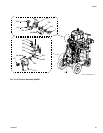
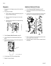
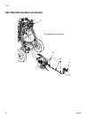
Replace Over Pressure Relief Valves
1. Flush before repairing equipment, if possible. See
Empty and Flush Entire System (new system or
end of job), page 29.
2. Follow Pressure Relief Procedure, page 22.
3. Ensure handle (312) is in the down position.
Remove the screws (313), jam nut (304), handles
(311), handle rod (312), clips (318), and
springs (320).
4. Unscrew both over pressure relief valves (302) from
the manifold.
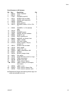
NOTE: The correct over pressure relief valve must be
used on all systems. Choose the correct color coded
valve from the chart on page 39.
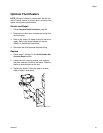
5. Apply blue threadlock to new over pressure relief
valves (302) and install in the manifold. Torque to
28-32 ft-lb (38-43 N•m).
6. Place a spring (320) over each valve stem. Place a
clip (318) in each valve stem groove to retain the
springs.
36
306
r_571101_3a0420a_38a
F
IG
. 11: Fluid Circulation Manifold
37
35
1
r_571101_3a0420a_39a
312
311
313
302
302
318
318
r_258988_3a0420a_2b
311
313
304
320
302
320
304