


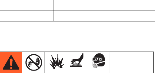
Maintenance
32 3A0420T
Maintenance
Hose Electrical Resistance
Check electrical resistance of hoses regularly. If total
resistance to ground exceeds 29 megohms, replace
hose immediately.
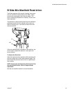
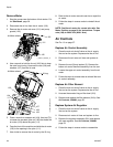
Filters
Once a week check, clean, and replace (if needed) the
following filters.
• Both pump filters; see lower manual for instructions.
• Main air inlet manifold filter; see Replace Air Filter
Element, page 36.
• Spray gun handle filter; see spray gun manual.
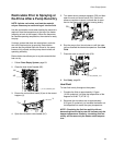
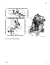
Seals
Once a week, check and tighten throat seals on both
pumps. See table for torque specifications. Be sure to
follow the Pressure Relief Procedure, page 22, prior to
tightening seals. There must be zero pressure on the
pumps when adjusting.
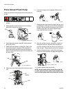
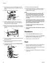
Cleaning Procedure
1. Ensure all equipment is grounded. See Grounding,
page 18.
2. Ensure the area where the system will be cleaned is
well ventilated and remove all ignition sources.
3. Turn off all heaters and allow equipment to cool.
4. Flush mixed material. See Flush Mixed Material,
page 28.
5. Relieve pressure. See Pressure Relief Procedure,
page 22.
6. Shutdown the sprayer and turn off all power. See
Shutdown, page 30.
7. Clean the external surfaces only using a rag soaked
in solvent that is compatible with the spray material
and surfaces being cleaned.
8. Allow enough time for the solvent to dry before
using the system.
Recommended Spare Parts
Keep these spare parts on hand to reduce downtime.
See Recommended Spare Parts, page 54.
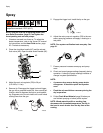
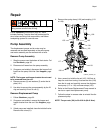
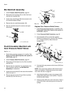
Change the Mix Ratio
In order to change the mix ratio, one or both pumps
need to be replaced, the air motor needs to be re-posi-
tioned, and the over pressure relief valves may need to
be installed.
NOTE: Only Xtreme XP lower pumps come with a
rod coupling.
1. Check the Varying Parts table on page 51 for the
correct pump sizes.
2. Remove and replace pump. See page 35.
3. Adjust the position of the air motor. See page 20.
4. If changing from one type of XP system to
another (for example - changing from XP35 to
XP70 or from XP70 to XP35): remove the existing
over pressure relief valves (302) and install the cor-
rect valves for the new system type. See Replace
Over Pressure Relief Valves on page 38.
5. Change air pressure relief valve as required,
depending on ratio. See air relief valve (64) in tables
starting on page 46.
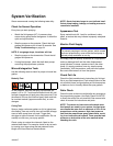
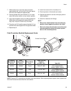
Pump Size Torque Specification
All 25-30 ft-lb (34-41 N•m)