


Operation
3A0732J 11
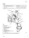
2. See F
IG
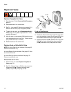
. 2. Close gun air regulator (E) and pump air
regulator (F) by turning knobs counterclockwise
reducing pressure to zero. Close bleed-type air
valve (D).
3. Connect air line to bleed type air valve.
4. Check that all fittings throughout system are tight-
ened securely.
5. Position pail close to pump. Suction hose is 3 ft
(0.9 m) long. Do not stretch hose tight; let it hang to
assist fluid flow into pump.
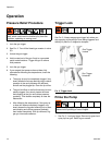
6. Hold metal part of gun firmly to side of grounded
metal pail, unlock trigger, and hold trigger open.
7. Open bleed-type air valve. Slowly turn pump air reg-
ulator clockwise, increasing pressure until pump
starts.
8. Cycle pump slowly until all air is pushed out and
pump and hoses are fully primed.
9. Release gun trigger and lock trigger safety. Pump
should stall against pressure.
Install the Spray Tip
Follow Pressure Relief Procedure, page 10. Install the
spray tip and tip guard as explained in your separate
gun manual, supplied.
The fluid output and pattern width depend on the size of
the spray tip, the fluid viscosity, and the fluid pressure.
Use the Spray Tip Selection Chart in your gun instruc-
tion manual as a guide for selecting an appropriate
spray tip for your application.
NOTE: The maximum recommended spray tip size is
.019 in. (0.483 mm).
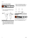
Adjust the Atomization
NOTE: Use this procedure with airless and air-assisted
spray guns.
1. Do not turn on atomizing air supply. Fluid pressure
is controlled by the air pressure supplied to the
pump (pump air regulator). Set fluid pressure at low
starting pressure. For low viscosity fluids (less than
25 sec, #2 Zahn cup) with lower percent solids (typi-
cally less than 40%), start at 300 psi (2.1 MPa, 21
bar) at pump outlet. For fluids with higher viscosity
or higher solids content, start at 600 psi (4.2 MPa,
42 bar). Refer to the following example.
Example:
2. Hold gun perpendicular and approximately 12
inches (304 mm) from surface.
3. Move gun first, then pull gun trigger to spray onto
test paper.
4. Increase fluid pressure in 100 psi (0.7 MPa, 7 bar)
increments, just to the point where a further
increase in fluid pressure does not significantly
improve fluid atomization. Refer to the following
example.
Example:
5. If you are using an air-assisted spray gun, see
Adjust the Spray Pattern on page 12.
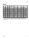
Pump
Ratio
Pump Air
Regulator Setting
psi (MPa, bar)
Approximate
Fluid Pressure
psig (MPa, bar)
15:1 x 20 (0.14, 1.4) = 300 (2.1, 21)
30:1 x 20 (0.14, 1.4) = 600 (4.2, 42)
Pump
Ratio
Pump Air Regulator
Increment
psi (MPa, bar)
Incremental
Fluid Pressure
psi (MPa, bar)
15:1 x 7 (.05, 0.5) = 100 (0.7, 7.0)
30:1 x 3.3 (0.02, 0.2) = 100 (0.7, 7.0)