


Repair
16 3A0732J
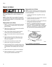
Disassemble the Pump
NOTE: Pump Repair Kits are available. See page 31 to
order the correct kit for your pump. Parts are marked
with an ‡.
1. Follow the instructions under Disconnect the Dis-
placement Pump, page 15.
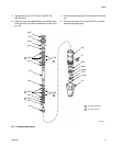
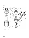
1. See F
IG
. 7. Loosen the packing nut (103), using a
screwdriver and hammer. Remove the o-ring (104).
2. Unscrew the cylinder (105) from the intake housing
(110). The rod and piston assembly will come with
the cylinder.
3. Remove the ball guide (109), intake ball (116), seat
(117), and o-ring (111) from the intake housing
(110).
4. Drive the rod and piston assembly out the bottom of
the cylinder. Remove the o-ring (107) from the cylin-
der.
5. Insert a plastic rod in the bottom of the cylinder and
drive the throat packings and glands out the top.
6. Put the rod (119) in a vise and unscrew the piston
(124). Be careful not to drop the piston ball (120).
Disassemble the piston packings from the piston.
7. Clean and inspect all parts. Replace any damaged
parts.
Reassemble the Pump
NOTE: Soak the leather packings (113‡, 125‡) in
hydraulic oil for one hour before installing them in the
pump.
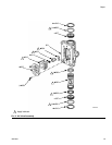
1. Install the piston wiper (123‡) on the piston (124),
with the lips facing down. Install the female gland
(122‡). Install the piston packings in the following
order with the lips facing up: blue UHMWPE (126‡),
leather (125‡), UHMWPE, leather, UHMWPE.
Install the male gland (121‡).
2. Put the displacement rod (119) in a vise. Place the
piston ball (120‡) in the cavity of the rod. Screw the
piston assembly into the rod. Torque to 24-30 ft-lb
(33-40 N•m).
3. Install the male gland (114‡) in the cylinder (105).
Install the throat packings in the following order with
the lips facing down: blue UHMWPE (106‡), leather
(113‡), UHMWPE, leather, UHMWPE. Install the
female gland (112‡).
4. Install the o-ring (104‡) on the packing nut (103).
Loosely install the packing nut in the cylinder.
5. Liberally lubricate the piston packings and the top 2
in. (51 mm) of the displacement rod (119).
6. Push the displacement rod (119) into the cylinder
(105) from the bottom until the piston is completely
in the cylinder and the rod protrudes from the pack-
ing nut (103).
7. Grease the o-ring (107‡) and install it on the cylin-
der (105).
8. Install the o-ring (111‡), seat (117), intake ball
(116‡), and ball guide (109) in the intake housing
(110).
9. Place the intake housing (110) in a vise. Screw the
cylinder (105) into the intake housing. Torque to
70-80 ft-lb (95-108 N•m).
10. Tighten the packing nut (103) 1/2 turn past hand-
tight, or torque to 60-80 in-lb (6.7-9.0 N•m).
11. Ensure that the button plug (102‡) is in place on the
packing nut (103).
12. Follow the instructions under Reconnect the Dis-
placement Pump, page 16.
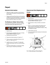
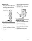
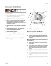
Reconnect the Displacement
Pump
1. Screw the displacement pump into the adapter plate
(10) until it stops. Back off pump less than 1 turn, to
align pump outlet as desired.
NOTICE
The displacement pump can be damaged if the stroke
is not centered when the pump is reconnected. Be
sure to fully screw the displacement pump into the
adapter plate (10).