


Repair
24 3A0732J
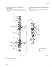
5. Lubricate and install the o-ring (202*) on the bottom
cover (201).
6. Carefully push the threaded end of the rod (218) up
through the bottom cover (201).
7. Apply 16G561 adhesive to the threads of the rod
(218). Screw the piston (219) onto the rod. Place
the piston in a vise with soft jaws and torque to
35-40 ft-lb (47-54 N•m).
8. Lubricate and install the o-ring (204*) on the piston
(219).
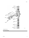
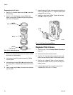
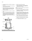
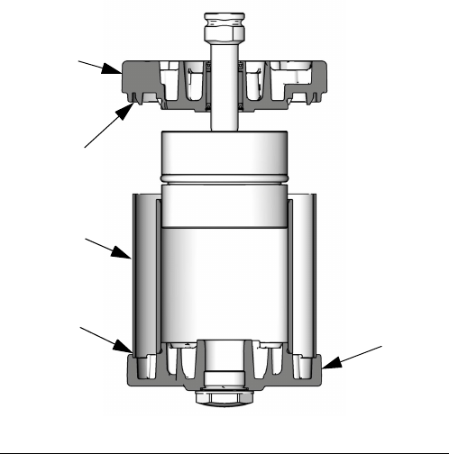
9. See F
IG
. 15. Carefully place the bottom cover/piston
assembly on the cylinder (205), sliding the piston
(219) into the cylinder. The manifold surfaces of the
top and bottom covers must align. Be sure the
shield (206) is in the groove on both the top and bot-
tom covers.
10. Install the tie bolts (212) hand tight.
11. Install two gaskets (208*) on the manifold (220).
Install the manifold (220). Torque screws (211) to
95-105 in-lb (10.7-11.9 N•m).
NOTE: The manifold is reversible for ease of placement
of muffler or remote exhaust.
12. Align the air valve gasket (209*◆†) on the manifold,
then attach the air valve (214). Torque screws (211)
to 95-105 in-lb (11-12 N•m).
13. Tighten the tie bolts (212) halfway. Work in a criss-
cross pattern. Check that the shield (206) remains in
the grooves on both covers. Continue tightening the
bolts in pattern to 11-13 ft-lb (15-18 N•m).
14.
On 3.5 in. motors only,
lubricate the o-ring (230*).
Install it and the plug (231) in the top cover (210).
15. Lubricate and install pilot valves (213) in top and
bottom cover. Torque to 95-105 in-lb (11-12 N•m).
16. See Reconnect the Air Motor on page 21.
F
IG
. 15. Align Shield in Grooves on Covers
groove
groove
201
206
ti16281a
210