


Installation
3A0732J 7
Installation
Prepare the Operator
All persons who operate the equipment must be trained
in the safe, efficient operation of all system components
as well as the proper handling of all fluids. All operators
must thoroughly read all instruction manuals, tags, and
labels before operating the equipment.
Prepare the Site
Ensure that you have an adequate compressed air
supply.
Bring a compressed air supply line from the air com-
pressor to the pump location. Be sure all air hoses are
properly sized and pressure-rated for your system. Use
only electrically conductive hoses. The air hose should
have a 3/8 npt(m) thread. A quick disconnect coupling is
recommended.
Keep the site clear of any obstacles or debris that could
interfere with the operator's movement.
Have a grounded, metal pail available for use when
flushing the system.
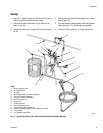
Supplied Components
See F
IG
. 2 on page 9.
• The red-handled bleed-type master air valve (D)
is required in your system to relieve air trapped
between it and the air motor and gun when the valve
is closed. Do not block access to the valve.
• The pump air regulator (F) controls pump speed
and outlet pressure by adjusting the air pressure to
the pump.
• The air pressure relief valve (P) opens automati-
cally to prevent overpressurization of the pump.
• The gun air regulator (E) adjusts the air pressure
to the air-assisted spray gun.
•The spray gun (H) dispenses the fluid. The gun
houses the spray tip (not shown), which is available
in a wide range of sizes for different spray patterns
and rates of flow. Refer to gun manual for tip instal-
lation.
•The red hose (G) provides the gun air supply.
•The blue hose (K) provides the gun fluid supply.
•The suction kit with strainer (J) allows the pump
to draw fluid from a 5 gallon (19 liter) pail.
Inline Fluid Filter Kits
Inline fluid filter kits are available as an accessory in
stainless steel (24F271) or aluminum (24F272), to filter
particles from fluid as it leaves the pump. Kits include a
60 mesh (250 micron) stainless steel element.
Air Line Accessories
Install the following accessories in the order shown in
F
IG
. 2, using adapters as necessary.
•An air-line filter (C) removes harmful dirt and mois-
ture from the compressed air supply.
• A second bleed-type air shutoff valve (B) isolates
the air line accessories for servicing. Locate
upstream from all other air line accessories.