


10
307-712
OPERATION
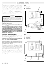
Adjust the Spray Pattern
Follow
the steps
below to establish the correct fluid flow
and
air flow
.
DO NOT
turn the turbine air on yet.
1. Adjust the fluid flow for the appropriate flow rate by
using
the
fluid pressure regulator installed in the fluid
line.
Check the fluid nozzle chart in manual 307–803
for
the appropriate flow rate for the air cap. Start with
the
lowest rate shown
and increase it until you get the
desired
flow rate.
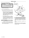
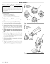
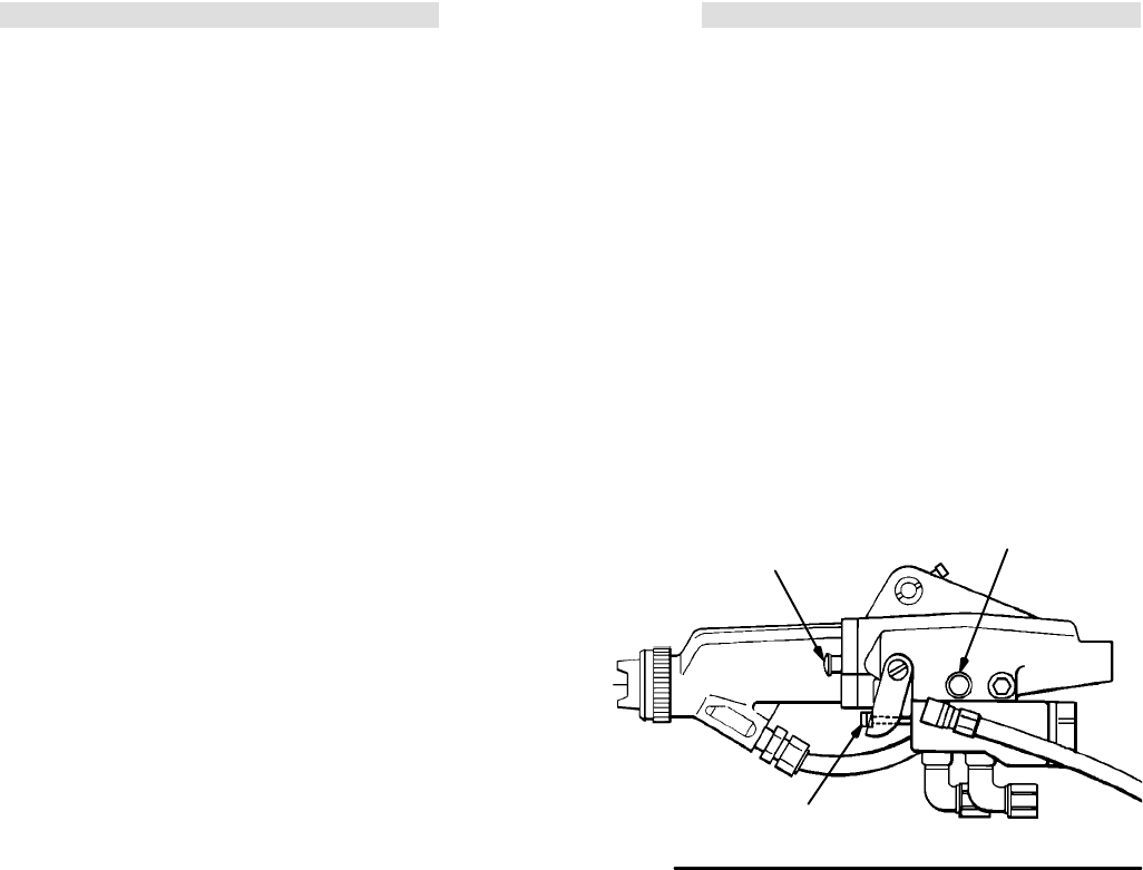
2. For fine adjustment of how much fluid is sprayed,
tighten or loosen the trigger adjusting nut (24). See
Fig
4. T
urn the nut
out
to reduce
the
amount of fluid
sprayed
or turn it
in to increase
the amount.
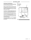
3. Close the fan adjusting knob (56) by turning it fully
clockwise
.
4. Use
an air pressure regulator to adjust the degree of
atomization.
Always use the lowest air pressure pos
-
sible
for the most ef
ficiency.
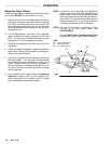
5. Use the
fan adjusting knob
to change the shape of
the spray pattern. Turn the knob
counterclockwise
for a wide pattern and
clockwise
for a solid, round
pattern. When increasing to a wide, flat pattern, it
may be necessary to increase the supply of fluid to
the gun to maintain the same amount of coverage
over
a large area.
6. First, complete all the checks under the Operating
Checklist on page 9. Then turn the turbine air on.
When spraying, the
ES indicator light
(51) should
glow,
indicating the electrostatic charge.
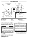
NOTE: Provide
a 3.1 bar (45
psi) clean, dry
, regulated air
supply
to the gun to
ensure full voltage from the
power
supply
. The gun may be operated at lower
turbine
air pressure, but may lose some
electro
-
static
ef
fect. Do not operate the turbine at an
air
pressure
greater than 3.1 bar (45 psi) as there
is
no
benefit and turbine life will be reduced.
NOTE: A remote fan air adapter is available to control
the fan air at the control booth. See
ACCESSORIES.
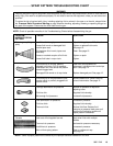
See
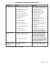
the
Spray Pattern T
roubleshooting Chart
on
page 13 to correct spray pattern problems.
Fig 2
KEY
24 Trigger
Adjusting Nut
51
ES Indicator Light
56
Fan Adjusting Knob
Fig
3
Fig 4
51
24
56