


7
307-712
INSTALLATION
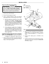
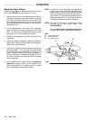
Mount the Gun
Mount
the gun on a stationary
support or on a reciprocat
-
ing
arm. The mounting rod must be
properly
grounded
.
Mount
the gun so the front of the gun is 254 to 300 mm (10
to
12 in.) from the work piece.
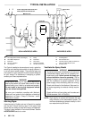
Connect the Air Line (Refer
to the T
ypical
Installation Drawing)
WARNING
To
reduce the risk of
electric shock or other serious
bodily
injury
,
the air supply hose must be electrically
connected
to a true earth ground.
Use Only Graco
Electrically Conductive Air Supply Hose. This
hose,
and the gun, have special threads which pre
-
vent
using any other type of hose with the gun.
See
the
ACCESSORIES
section to order the hose.
1. Install
an air line filter (K) and an air and water sepa
-
rator
(B) on the main air line to ensure a dry
, clean air
supply
to the gun. Dirt and moisture can ruin the ap
-
pearance
of your finished workpiece and can cause
the
gun to malfunction.
2. Install
an air line lubricator (D) close to the pump air
inlet.
3. Install a normally closed, 3-way air solenoid (P) or
manual
valve on the
turbine, cylinder and remote fan
air
supply lines.
(The remote fan line is optional.)
4. Install a bleed-type air regulator (E) on the pump,
turbine,
atomizing, cylinder
, and remote fan
(option-
al)
air supply lines to control air pressure to the pump
and
gun.
5. Install
a bleed-type air shutof
f valve (A) on the main
air
line, the pump line, and each gun air supply line to
shut
of
f air to the pump and gun.
WARNING
The
bleed–type
air shutoff valve
(A) is required in
your system to relieve air trapped between this
valve and the pump after the air regulator is
closed. Trapped air can cause the pump to cycle
unexpectedly,
which could result in serious bodily
injury,
including splashing in the eyes or on the
skin
and
injury from moving parts.
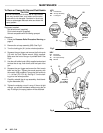
6. Connect
the cylinder air line to the gun’
s cylinder air
inlet (marked CYL).
7. Connect
the atomizing air
line to the gun’
s atomizing
air
inlet (marked
ATOM).
8. Connect
the turbine air supply line to the gun’
s air in
-
let (marked ES).
The gun air inlet fitting has a left
hand thread.
Connect the air supply hose ground
wire
to a true earth ground.
9. A
remote
fan air adapter is available to control the fan
air
at the control booth. See
Installing the Optional
Remote
Fan Air Adapter
, on page 8.
Connect the Fluid Line (Refer
to the T
ypical
Installation Drawing)
1. Before connecting the fluid line, blow it out with air
and flush it with solvent. Use solvent which is com-
patible
with the fluid to be sprayed.
2.
Install a fluid regulator (L) on the fluid line to control
fluid pressure to the gun.
3. Install
a fluid filter (G) and drain valve (H) at the pump
outlet.
WARNING
The
fluid drain valve
(H) is required in your system
to
assist
in relieving fluid pressure in the displace
-
ment pump, hose and gun; triggering the gun to
relieve pressure may not be sufficient. Install a
drain
valve close to pump’
s fluid outlet. The drain
valve
reduces the risk of property damage or seri
-
ous
bodily injury
, including splashing in the eyes or
on
skin and contamination from hazardous fluids.
4. Connect
the fluid line to the gun fluid inlet.
CAUTION
Do
not use metal fittings at the gun barrel. For cir
-
culation
systems, use plastic fittings.