


12
307-730
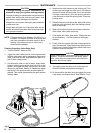
Pressure
Relief Procedure
To
reduce the risk of serious bodily injury
, including
injury from moving parts, or electric shock, always
follow
this procedure whenever you shut of
f the
sys
-
tem,
when checking or servicing any part of the sys
-
tem
and whenever you stop painting
.
1. T
urn the ON/OFF switch to OFF
.
2.
Unplug the power supply cord.
3. T
rigger the roller valve to relieve pressure.
If
you suspect that pressure is not fully relieved after
following
the steps above,
open the priming valve
2
turns
counterclockwise.
WARNING
WARNING
These
repair procedures should be performed only
by qualified repair person with an electrical back-
ground,
using the proper tools. Failure to
do the pro
-
cedures correctly can result in electric shock, or oth
-
er
serious injury and damage to the pump.
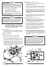
NOTE: For
all electrical repair
, follow the
Pressure Re
-
lief Procedure W arning above. Then remove
the
base cover (42). Before checking or operat
-
ing
the system, reinstall the base cover
, making
sure
all wires are tucked in neatly
.
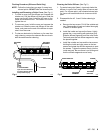
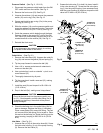
Fuse
(See Fig 10
.)
1. Pull
the old fuse out of the fuse holder (65). Install a
new
fuse (67).
Be sure you install ONL
Y a 3AG fuse,
rated
at 1–1/4 amps.
Rectifier
(See Fig 1
1.)
1.
Disconnect the four leads from the rectifier
.
2.
Remove the screw (33) and rectifier (39).
3. Install a new rectifier so the positive terminal (+) is
closest
to the fuse holder (65). Install the screw (33).
4. Connect
the power supply cord’
s white lead to an un
-
marked terminal. Connect the pressure switch lead
to the other unmarked terminal. Connect the black
motor lead to the negative (–) terminal, and the red
motor
lead to the positive (+) terminal.
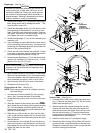
ON/OFF Switch
(See Fig 10
and 1
1.)
1. Disconnect the two leads from the ON/OFF switch
(34)
terminals. See Fig 1
1.
2. Remove
the boot (36) and pull the switch (34) out of
the base. Remove
the ground wire (84). See Fig
10.
3. Remove the top nut (A) from the new switch. Place
the
ground wire connector (84) on the switch and re
-
install
the nut. Install the new switch, aligning the tab
in the base
with
the slot in the switch. See Fig
10
. In
-
stall
the boot.
4. Connect a pressure switch lead to the power-OUT
terminal, and a jumper wire lead to the power-IN
terminal.
See Fig 1
1.
Power Supply Cord
(See Fig
10
and 1
1.)
1. Disconnect
the white lead from the rectifier (39), and
the black lead from the fuse holder (65), and the
green
lead from the grounding screw (82).
2. From the inside of the base, use a screwdriver to
push the strain relief bushing (38) out of the base.
Remove
the bushing and power supply cord.
3. Slide the strain relief bushing over the new power
supply cord. Press the bushing together and then
press
the bushing into the base.
4. Connect the green ground wire to the grounding
screw
(82) and secure it with a washer (81) and nut
(80). Connect the black lead to the fuse holder (65)
and the white lead to an unmarked terminal on the
rectifier (39).
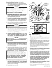
WARNING
To maintain grounding continuity in your system,
and
to
reduce the risk of electric shock, check to be
sure
the ground wires are properly connected. The
power
supply cord’
s green ground wire connects
to
the screw (82), and the ground wire (84) connects
between the ON/OFF switch and the screw (82).
Also be sure the screws (25 and 33) are tightly
screwed
into the base. See Fig 10 and 1
1.
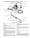
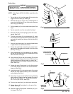
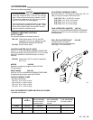
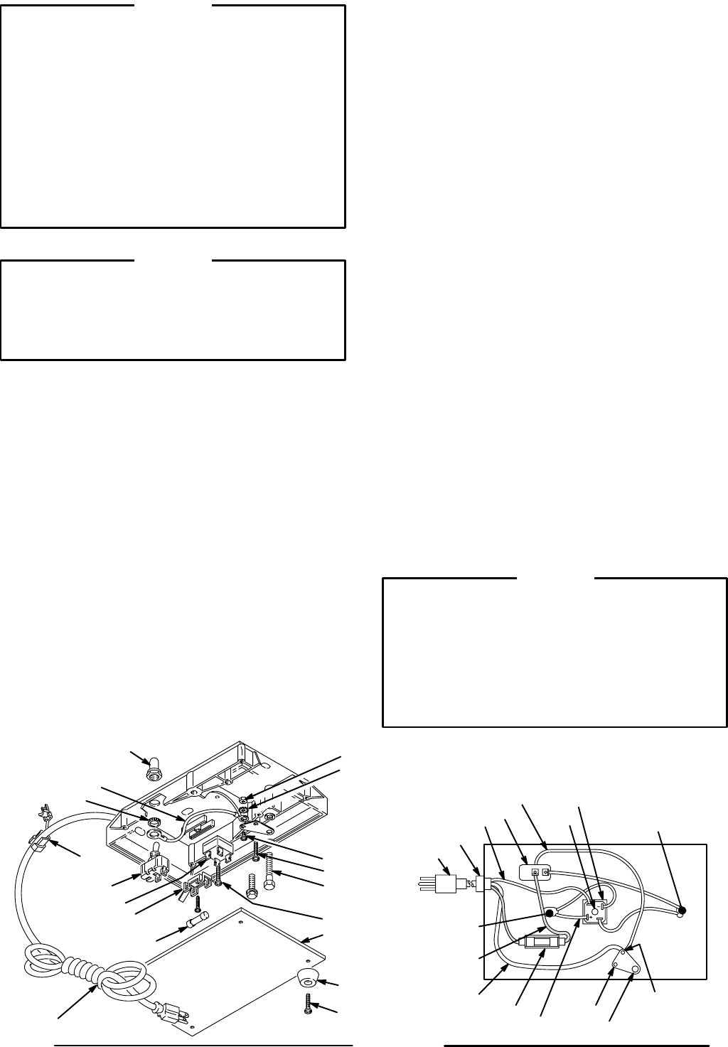
Fig 10
36
38
37
34
39
33
25
65
67
82
80
81
A
0294
33
43
42
33
84
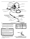
Fig 11
37
38
34
65
25
82,81,80
39
33
33
PRESSURE
SWITCH
(2)
LEADS
JUMPER
WIRE
WHITE
IN
OUT
MOTOR
LEADS
RED
GREEN
GROUND
WIRE
0295
84