


14
307-730
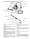
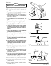
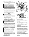
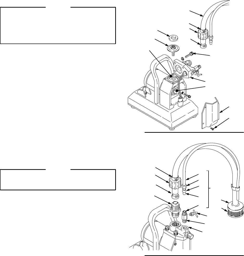
Diaphragm (See
Fig 14
.)
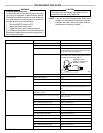
CAUTION
Replace the diaphragm whenever you remove the
pump housing (9), or after each 100 hours of use,
whichever comes first. During use, small grooves
are formed in the diaphragm which cannot be re-
aligned properly. Reusing a diaphragm may cause
leaking,
resulting in costly pump damage.
1. Remove the screws (15). Tip the pump housing (9)
back, being careful not to damage the wires. Re-
move
the front cover (23).
2. Check
the diaphragm guide (1
1) in the
bottom of the
pump housing (9) and replace it if is worn or dam-
aged.
Clean the pump housing thoroughly
. Press the
new
guide, flat
side first, into the housing,
using only
your
fingers.
Be sure it is installed evenly
.
3. Screw
the diaphragm (17)
out of the connecting rod
assembly (18).
4. Use
a soft
brass or nylon bristle brush to clean the top
of the connecting rod and housing. Taking care not
to
damage the diaphragm grooves, gently clean the
bottom
of the pump housing (9).
5. Check
the rod, motor bearing and eccentric. If there
is
any
paint
or damage,
clean or replace the connect
-
ing
rod assembly as explained on page 15.
6. Screw the new diaphragm (17) into the connecting
rod
just until it
bottoms out.
Then turn it 1/8 – 1/4 turn
[about
4–6 in–lb (0.4–0.7 N.m)].
CAUTION
Never
turn the diaphragm more than 1/4 turn when
torquing it, as that will prevent the diaphragm from
working
properly
.
7.
Apply thread lubricant to the screws (15) and install
them
with
the lockwashers (16) in the pump housing.
Torque the screws a few inch–pounds (N.m) at a
time,
oppositely and evenly
, to 85 in–lb (9.6 N.m).
8.
Spin the motor shaft (D) to be sure it turns freely
.
9.
Reinstall the front cover (23).
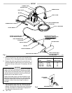
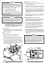
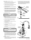
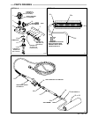
Priming V
alve & T
ube
(See Fig 15
.)
NOTE: Each new priming valve kit includes a priming
tube
and fittings.
1. Unscrew the nut on the handle (E) of the priming
valve
(10a). Unscrew the stem of the handle.
2. Screw
the priming valve (10a) out of the pump hous
-
ing (9).
3. Wrap the threads of the priming valve with r
tape.
Screw the valve
snugly into the pump housing
(9). The valve handle should be parallel with the
angled
edge of the housing to avoid interference with
the
inlet or outlet valves.
4. Slide the nut (10d) and ferrule (10c) onto the tube
(10e).
Install the tube support (10b) in the end of the
tube.
Screw the nut onto the priming valve, which will
seat
the ferrule.
5. Screw the stem of the handle (E) onto the priming
valve
until it bottoms, and then back it out two turns.
Hand
tighten the nut onto the priming
valve, and then
tighten
the stem into the valve.
Fig 14
44
45
47
46
11
17
18
9
23
24
D
LUBRICATE
THREADS;
TORQUE
T
O
85 in–lb (9.6 N.m)
0298
15,16
Fig
15
45
46
1
9
10
10e
10d
10c
10b
10a
WRAP
WITH
T
APE
0786
E
47
48
49
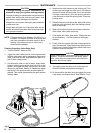
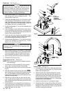
Suction Tube
(See Fig 15.
)
1. Unscrew
the nut (45) from the fluid inlet valve
hous
-
ing
(1). Remove the hose clamp (47). Slit the suction
tube
to free the nipple (46).
2. With the nipple (46) inserted through the nut (45),
dampen the new hose (44) with warm water and
press the hose over the nipple. Screw the nut onto
the inlet valve housing (1). Press the hose further
onto the nipple, leaving about a 1/8 in. (3 mm) gap
between
the nut and hose end.
3.
Install the hose clamp (47) and tighten snugly
.
4. Remove
the filter housing (48)
and filter (49) from the
old suction hose. Install these parts on the new hose.
Dampen
the hose with warm water to ease the filter
and
filter housing onto the hose.
PTFE
PTFE
PTFE
PTFE
PTFE
PTFE