


5
307-730
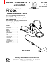
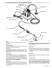
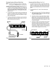
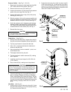
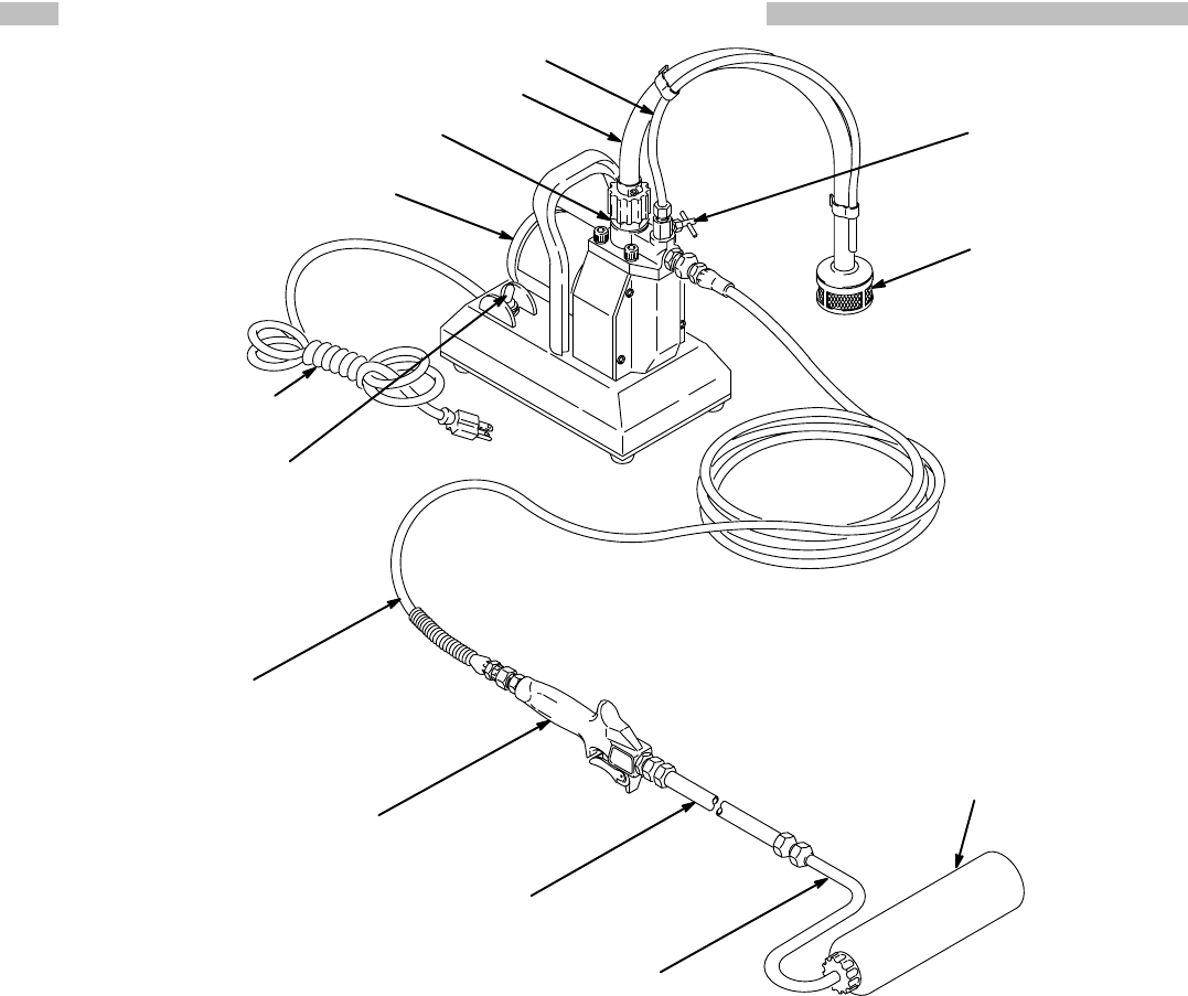
PT2000 PRESSURE ROLLER SYSTEM DESCRIPTION
SUCTION
HOSE
PRIMING TUBE
INLET V
ALVE
MOTOR
ON/OFF SWITCH
POWER SUPPL
Y CORD
ROLLER V
ALVE
PRIMING V
ALVE
P
AINT FIL
TER
25 FT
. (7.6 M) HOSE
18 INCH EXTENSION
9 INCH ROLLER FRAME
ROLLER COVER
0285
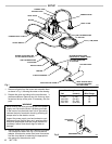
Motor
The motor drives the connecting rod which moves the
diaphragm.
Pressure
Switch
The pressure switch at the pump outlet turns the motor
on
and of
f to control paint
pressure.
Diaphragm
The diaphragm is the heart of the pump. Driven by the
connecting rod and motor , the movement of the dia-
phragm
draws paint
through the suction hose and to the
outlet
valve.
Priming V
alve
The priming valve assists in priming the pump during
startup. Turning the priming valve counterclockwise
causes the paint to drain directly back into the pail
through the priming tube. T urning the knob clockwise
causes
the paint
to flow through the fluid outlet valve
and
to
the hose, roller valve and extension
.
Outlet V
alve
The outlet valve has a ball check which prevents paint
from flowing backwards into the pump. This helps keep
an
even supply of paint
to the roller each time you
trigger
the roller
valve.
Inlet V
alve
As
the diaphragm draws paint from the suction tube, the
paint
passes through the inlet
valve which opens to allow
paint
into the pump.
Outlet Hose
The hose has swivel-type couplings for easy assembly.
A
larger diameter outlet hose and chemical-resistant out
-
let
and suction hoses are available. See ACCESSORIES
on
page 19.
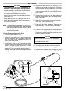
Roller
V
alve
The
roller
valve controls paint
flow to the
roller
by trigger
-
ing
it on and of
f.
Pressure Roller
The
pressure roller has an 18 inch extension. T
wo roller
covers, one 1/2 inch nap for smooth surfaces, and one
3/4”
nap for semi–rough surfaces, are provided. Dif
ferent
lengths
and adjustable extensions and
dif
ferent types of
roller
covers are available. See
ACCESSORIES on page
19.