


15
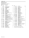
307-730
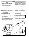
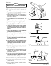
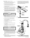
Connecting Rod and Bearing
(See Fig 16
.)
1. Remove the front cover (23). Remove the screws
(15).
Carefully tip back the pump housing. Unscrew
the diaphragm (17) and discard it.
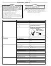
CAUTION
Replace the diaphragm whenever you remove the
pump housing (9), or after each 100 hours of use,
whichever comes first. During use, small grooves
are formed in the diaphragm which cannot be re-
aligned properly. Reusing a diaphragm may cause
leaking,
resulting in costly pump damage.
2. Remove the motor screws (20). Lift the motor (30)
slightly. Holding the connecting rod (18a), pull the
motor
away from the housing (22).
3. Inspect
the bearing (18b) in the connecting rod (18a).
If
it is worn or any rollers are broken, replace the
con
-
necting
rod assembly (18). Inspect the motor eccen
-
tric,
and replace the motor if the eccentric is worn.
4. Use
your fingers to
pack high quality bearing grease
thoroughly
in between the bearing rollers.
CAUTION
Thoroughly
grease the bearing to extend the life of
the bearing and the motor eccentric.
5. Use
a soft
brass or nylon bristle brush to clean the top
of the connecting rod and housing. Taking care not
to
damage the diaphragm grooves, gently clean the
bottom
of the pump housing (9).
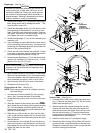
6. Install
the connecting rod assembly (18)
in its hous
-
ing
(22).
Screw a new diaphragm (17) into the rod just
until it bottoms. T urn the diaphragm another 1/8 to
1/4
turn [about 4–6 in–lb (0.4–0.7 N.m)].
CAUTION
Never
turn the diaphragm more than 1/4 turn when
torquing it, as that will prevent the diaphragm from
working
properly
.
7. Align the motor with the pins in the connecting rod
housing
(22). Guide the motor shaft (A) through the
connecting
rod bearing (18b).
Spin the motor shaft to
be
sure it moves freely
.
8. Loosely
install the lockwashers (21)
and screws (20)
to hold the motor. Spin the motor shaft again. Alter-
nately
tighten the screws. Spin the motor shaft
again.
CAUTION
Spinning the motor shaft while assembling the
pump
ensures that parts
are properly aligned. If they
are not, and you start the pump, serious damage
could result to the motor , bearing and connecting
rod. If you feel binding or resistance, disassemble
the parts, checking the spin often, until you deter-
mine
and correct the cause of the binding.
9. Position
the pump housing (9) on the connecting rod
housing.
Lubricate the screws (15)
and loosely install
them and the lockwashers (16). Torque the screws
a few inch–pounds (N.m) at a time, oppositely and
evenly,
to 85 in–lb (9.6 N.m).
10.
Reinstall the front cover (23).
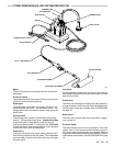
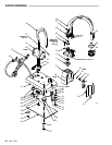
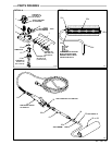
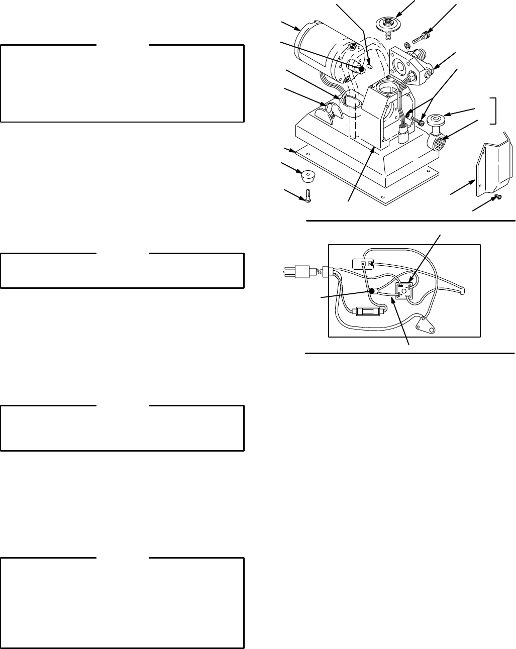
Fig 16
17
9
0300
LUBRICATE
TORQUE
T
O
85 in–lb
(9.6 N.m)
15,16
42
43
33
22
24
23
69
34
30
21,20
18a
18
18b
QTY 2
PRESS
FIT INT
O 22
GREASE
BEARING
HEAVILY
A
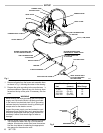
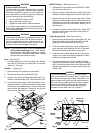
Fig
17
39
IN
OUT
RED
(+)
MOTOR
LEADS
0295
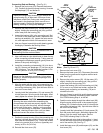
Motor (See
Fig 16
and 17
.)
1.
Remove the front cover (23).
2. Remove the base cover (42). Disconnect the motor
leads from the positive and negative rectifier termi-
nals.
See Fig 17
.
3. Remove the motor screws (20). Lift the motor (30)
slightly. Holding the connecting rod (18a), pull the
motor
away from the housing (22).
4. Inspect
the bearing (18b) in the connecting rod (18a).
If it is worn or any rollers are broken, replace the
bearing and connecting rod assembly (18) as in-
structed
to the left.
5. Use
your fingers to
pack high quality bearing grease
thoroughly in between the bearing rollers. See the
CAUTION
following Step 4, to the left.
6. Feed the motor leads through the rubber boot (69).
Align the motor with the pins in the connecting rod
housing
(22). Guide the motor shaft (A) through the
connecting
rod bearing (18b).
Spin the motor shaft to
be
sure it moves freely
.
7. Loosely
install the lockwashers (21)
and screws (20).
Spin the motor shaft again. Alternately tighten the
screws. Spin the motor shaft again. See the
CAUTION,
following Step 8, to the left.
8. Connect
the red motor lead to the positive (+) termi
-
nal
and the black motor lead to the negative (–) termi
-
nal
of the rectifier (39). See Fig 17
.
9. Install
the base
cover (42) and bumpers (43), and the
front cover (23).