


307-724
18
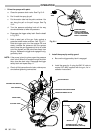
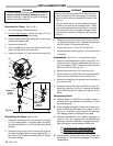
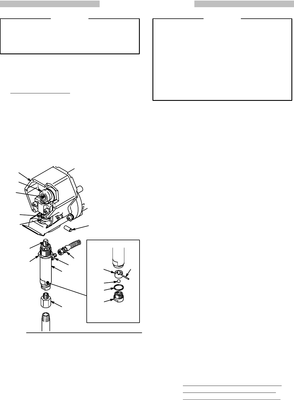
DISPLACEMENT PUMP
To
reduce the risk of serious bodily injury, follow the
Pressure Relief Procedure Warning on page 16
before checking or repairing any part of the spray
system.
Unplug the sprayer!
WARNING
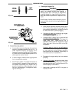
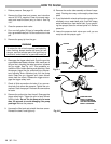
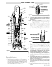
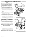
Removing the Pump.
See Fig 18–1.
1.
Flush the sprayer
. Relieve pressure.
2. For the upright sprayer, remove the clips (110,114)
and
drain tube (125) from the pump.
3. Hold
the intake valve (222) steady with
a wrench and
unscrew
the adapter (38).
4.
Unscrew the hose (52).
5. Use a screwdriver to push the retaining spring (33)
aside,
and then push out the pin (34).
6. Loosen
the locknut (1
12) and unscrew the pump
(58).
Fig
18–1
222
*206
*204
207*
215
52
33
34
58
223
A
36
55
10
TORQUE
T
O
70 ft–lb
(95 N.m)
112
TORQUE TO
80 ft–lb
(107 N.m)
54
38
INT
AKE V
AL
VE DET
AIL
06780678
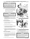
Reinstalling the Pump. See
Fig 18–1.
1. Rotate
the crankshaft (A) so the connecting rod (54)
is in its lowest position. The pump piston rod (223)
should
protrude about 1 in. (25 mm)
above the pump
cylinder.
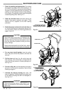
2. Screw the pump into the drive housing (55) until the
pin
holes are
aligned with the pump coupling (36). In
-
sert
the
pin (34). Position the spring (33) so it covers
the
ends of the pin.
Be
sure the retaining spring (33) is firmly and com
-
pletely
in the groove of the connecting rod to
prevent
the
pin (34) from working loose due to vibration. See
Fig
18–1.
If the pin works loose, it or other parts could break
off due to the force of the pumping action. These
parts could be projected through the air and result
in
serious bodily injury or property damage, includ
-
ing
damage to the pump, connecting
rod or bearing
housing.
WARNING
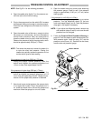
3.
Screw
the pump further into the drive
housing (55) un
-
til
it stops at the locknut (1
12). Unscrew the pump just
until
the nipple (10) faces straight back.
4. T
orque the locknut (1
12) to 70 ft–lb (95 N.m).
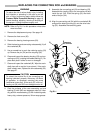
5. Reassemble
the remaining parts, in
the reverse order
of
removal.
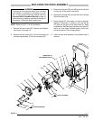
Disassembly.
See Fig 19–1
,
except where noted.
1. Remove
and disassemble the intake valve (222). If no
further service is needed, reassemble the valve, us-
ing a new gasket (206*). Torque the intake valve to
80
ft–lb (107 N.m). See Fig 18–1.
2.
Remove the packing nut (221) and plug (201).
3. Tap the piston rod (223) down with a plastic mallet.
Pull
the rod out the bottom of the cylinder (216).
4. Remove the packings and glands from the throat of
the
cylinder (216).
5. Clamp the flats of the piston rod (223) in a vise. Un-
screw the retaining nut (214). Unscrew the piston
valve (224) from the rod. Remove all parts from the
piston.
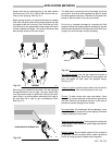
Reassembly Notes
A. Packing Repair Kit 222–587 is available. Parts in-
cluded
in the
kit are marked with an asterisk (*) in the
text
and drawings.
B. Clean all parts thoroughly. Check the outside of the
piston
rod (223) and the inside
of the cylinder (216) for
scoring or scratches, which prevent the packings
from
sealing properly
. Replace all worn parts.
C. Alternate polyethylene and leather packings as
shown in Fig 19–1, starting with the polyethylene
packings. Incorrect installation damages the pack-
ings
and results in pump leakage. Notice that:
the lips of the throat v–packings face down
;
the lips of the piston V–packings face up
;
the lips of the U–cup seal (205) face down
.
D. Coat
the piston rod and the
inside of the cylinder with
lightweight oil, and soak the packings in oil before
reassembling.