


307-724
22
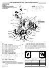
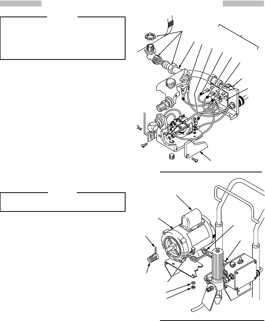
REPLACING THE ELECTRIC MOT
OR & CAP
ACITOR
To
reduce the risk of serious
bodily injury
, including
fluid injection or splashing in the eyes or on the
skin,
or injury from moving parts, always follow the
Pressure
Relief Procedure W
arning
on page 16
before
checking, adjusting, cleaning or shutting of
f
the
sprayer
.
Unplug the power supply cord.
WARNING
1.
Disconnect the hose at the displacement pump.
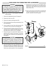
2. Remove
the drive assembly
. See page 21. The pump,
connecting rod and bearing can stay assembled to
the
drive assembly
.
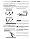
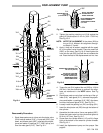
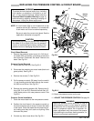
3. Drive
out the pin (27) and remove the gear (37). See
Fig
22–2.
4. Remove
the pressure control cover (41).
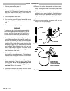
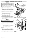
Disconnect
the
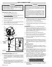
motor leads as shown in Fig 22–1.
5. Unscrew the connector (13 and 303) nuts on both
ends
of the conduit (1). See Fig 22–1.
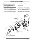
6. Remove
the motor mounting screws (7). Lift the mo
-
tor
and carefully guide the wires
through the pressure
control connector
(303).
Remove the conduit (1) from
wires.
See Fig 22–2.
CAUTION
Pull the motor leads through the conduit one at a
time
to avoid loosening the terminals.
7. Loosen the locknut and unscrew the connector (13)
from
the motor
. Do
not twist the wires.
See Fig 22–1.
8.
Install the new
motor in the reverse order of removal.
NOTE: Install the new circuit board (23f) which is in-
cluded with a new motor. Do not reuse the old
board.
See page 26 for installation.
Capacitor
1. Remove
the capacitor (23d)
cover
. See Fig 22–2. Re
-
move
the flag connectors from the old capacitor and
connect
them to the new capacitor
. Replace the cover
.
NOTE: The
replacement capacitor includes a new resis
-
tor,
installed.
0749
1
303
Fig 22–1
13
41
RED
BLACK
BROWN
23f
PINK
GREEN
& YELLOW
MOTOR
LEADS
27
37
7
23d
23
4
3
(located
under
this cover)
0675
Fig 22–2
1
303