


307-724 23
REPLACING THE PRESSURE CONTROL & CIRCUIT BOARD
To
reduce the risk of serious
bodily injury
, including
fluid injection or splashing in the eyes or on the
skin,
or injury from moving parts, always follow the
Pressure
Relief Procedure W
arning
on page 16
before
checking, adjusting, cleaning or shutting of
f
the
sprayer
.
Unplug the power supply cord.
WARNING
NOTE: A circuit board (23f) is not included with a new
pressure
control (50). However
, it is included
with
a
new motor and it can be ordered separately
.
Be
sure to order the correct circuit board. See
the
application
information on page 26.
Do
not allow the fittings (A) to move when removing
the elbow (312) or nipple (313) from the pressure
control, to avoid altering the factory setting of the
pressure
control or damaging
the pressure control.
CAUTION
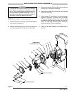
Circuit
Board Removal
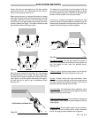
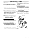
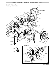
1. Remove
the pressure control
cover (41). Pull the cir
-
cuit
board (23f) out carefully
,
just enough to reach the
wire terminals. Disconnect the leads. Remove the
board.
See Fig 23–1.
Pressure Control Removal
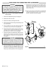
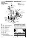
2.
Disconnect the hose (52). See Fig 23–2.
3. Disconnect
the remaining two motor
leads (black and
green/yellow).
See Fig 23–1.
4.
Remove the screws (7). See Fig 23–2
.
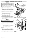
5. Pull the pressure control (50) away from the conduit
(1)
and carefully guide
the leads through the connec
-
tor
(303) one at a time. See Fig 23–1.
6. Remove the mounting bracket (40). Remove the fit-
tings
(302, 312, and 313). Remove the fluid filter (47).
Install these parts on the new pressure control.
See
Fig
23–2.
Pressure Control Installation
7. Guide
the motor leads into the new pressure control.
8. Position the circuit board in the pressure control so
the
wire connectors are at
the top. Connect the leads
to the board. Guide the leads into the pressure con-
trol, making sure they don’t catch on anything.
Slide
the
board into place.
9.
Connect any other loose wires. See Fig 23–1.
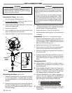
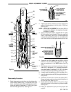
0749
RED
BLACK
BROWN
WHITE
GREEN
1
303
Fig 23–1
23f
13
41
PINK
BLACK
POWER
SUPPLY
LEADS
GREEN
& YELLOW
23c
MOTOR
LEADS
WHITE
RED
WHITE
TRIAC
LEADS
23
50
Fig
23–2
50
7
52
313
A
40
0677
41
312
302
47
10.
Mount the pressure control on the cart.
11. ADJUST
THE PRESSURE CONTROL!
See page 24.
Adjust the pressure control whenever a new or
used pressure control or circuit board is installed,
to
reduce the risk of overpressurization which can
result in component rupture, fire or explosion. Im-
proper adjustment may also prevent the sprayer
from
obtaining the maximum working pressure, re
-
sulting
in poor sprayer performance.
WARNING