


307-724
26
PARTS
DRA
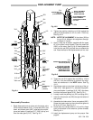
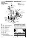
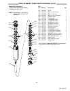
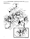
WING & LIST – PRESSURE CONTROL
Part
No. 215–860
Ref No. 50
Pressure Control Assembly
Includes replaceable items 301 to 316,
as listed below
NOTES:
Numbers with “Ref” preceeding
them correspond with the parts
lists on pages 28 and 30.
See wire colors in Fig 23–1.
Ref 23f
306
305
311
313
Ref 40
307
302
310
SEE
INFORMA
TION
BELOW FOR WHICH
CIRCUIT BOARD T
O
USE
LABEL
Ref
41
Ref 32
0749
301
Ref 23
304
Ref 25
312
LABEL
308
309
Ref 23c
303
Ref 13
315
1 316
Ref 23
Ref 121
314
Ref
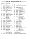
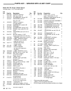
No. Part No. Description Qty
301 100–035 SCREW
, mach, pan hd, 8–32 x 5/16”
1
302 162–453*
NIPPLE, 1/4 npsm x 1/4 npt
1
303 102–932 CONNECT
OR, conduit, 90
_ 2
304 157–021 LOCKWASHER, int. shkprf, No. 8 1
305 217–492 CORD, power supply 1
306 108–295 RELIEF
, strain
1
307 178–035
}
LABEL, caution
1
308 100–072 NUT, hex, mscr
, 6–32
2
309 103–181 LOCKWASHER, No. 6 2
310 107–070 SCREW
, mach, flat hd, 6–32 x 5/8”
2
311 178–797
}
LABEL, warning
1
312 100–840* ELBOW
, street, 1/4 npt(f x m)
1
313 157–350*
ADAPTER, 3/8 npt x 1/4 npt
1
314 218–916 TRIAC 1
315 105–659 BOOT, switch 1
316 105–679 TOGGLE, switch 1
}
Extra warning labels available at no cost.
*
NOTE:
A new pressure control (50)
does not include items 302,
312,
313 or any items preceeded by “Ref” in the above
drawing.
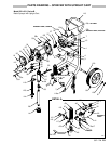
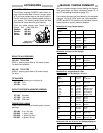
CIRCUIT
BOARD APPLICA
TIONS
Identify the correct circuit board for your sprayer by
matching the information below. The circuit boards may
be
purchased
separately
, but all replacement motors for
this
sprayer include a new circuit board.
105–683 223–597
Circuit Board P/N
and style
used
in used in
220–726,
A & B
231–001, A
Sprayer
, Series
220–726, C
231–001, B
218–949 Graco Motor P/N 224–727
Yes
External Motor Fan?
No
1112125400
Franklin Motor P/N
1101007414