


Model G0477 15" Planer/Moulder
-21-
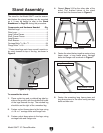
Setting Up Moulding
Guide Fence
Components and Hardware Needed: Qty
Wing Bolts
1
⁄4-20 x 1
1
⁄4" ...................................... 4
Flat Washers
1
⁄4" ................................................ 4
Cap Screw M5-.8 x 60 .......................................
2
Flat Washer 5mm ..............................................
2
Guide Fence Clamp ..........................................
2
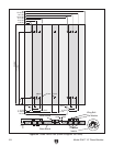
It is essential that you have a properly adjusted
guide fence in place when moulding. Figure 22
on Page 22 features a plan for creating your own
guide fence. W
e recommend using softwood or
plywood for guide fence construction.
To fasten the guide fence to the planer/mould
-
er:
1. UNPLUG THE PLANER/MOULDER FROM
THE POWER SOURCE!
2. Ensure that the threaded inserts indicated in
Figure 22 on Page 22 are firmly in place.
3. Raise the planer/moulder headstock to its
maximum height to provide working room.
4. Hand-fasten the guide boards to the base-
board using the wing bolts and flat washers.
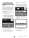
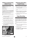
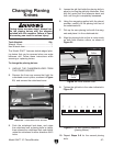
5. Fasten the baseboard to the table using the
cap screws, flat washers and clamps, as
shown in
Figure 21.
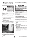
Figure 21. Clamp installation.
Extension
Table
Clamp
Main
Table
Cap
Screw
To adjust the guide fences to fit a workpiece:
1. UNPLUG THE PLANER/MOULDER FROM
THE POWER SOURCE!
2. Place the workpiece flush against the center
guide.
3. Adjust the guide boards to fit the workpiece,
allowing for smooth and even workpiece
movement throughout the guide fence.
4. Fully tighten the wing bolts to fasten the guide
boards in place.
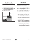
Adjusting Moulding
Guide Fence
Edge Moulding
Certain moulding tasks require the workpiece to
be oriented vertically, and thus extra-tall guide
boards are needed. Follow the plan shown
in
Figure 22 on Page 22, but increase the width of
the center guide and the guide boards from
1
⁄2"
to to
1".
To prepare the guide fence for edge mould
-
ing:
1. UNPLUG THE PLANER/MOULDER FROM
THE POWER SOURCE!
2. Replace the center guide and guide boards
with extra-tall guides
.
3. Follow Steps 2–4 of Adjusting Moulding
Guide Fence
on this page.