


-26-
G0512 Edge Sander
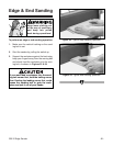
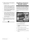
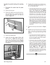
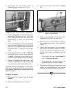
Figure 37. Tension nut flush with threads.
5. Turn the tension nut counter-clockwise until
the threads of the tension shaft are flush with
the nut, as shown in Figure 37.
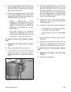
6. Loosen the tracking control bolt (Figure 36,
page 25).
7. Pull on the idler roller to take up the slack in
the tension shaft.
8. Tighten the tracking control bolt.
9. Turn the tension nut clockwise approximate-
ly three full turns.
10. Engage and disengage the belt tension
lever, then tighten the tension nut two more
full turns.
11. Adjust the idler roller-to-platen relationship
as described on pages 29-30.
12. Install the sanding belt and table, and track
the sanding belt before operating the
sander. Note—It may be necessary to slight-
ly adjust the tension nut to make the table fit.
Parallel Belt
Tracking
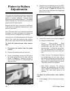
The belt should track on the rollers so that the top
edge of the sanding belt stays parallel with the
top edge of the platen graphite, as illustrated in
Figure 38.
Figure 38. Illustration of parallel belt tracking.
To check the parallel tracking of the sanding
belt:
Track the sanding belt, so that the side of the belt
that is tracking higher is even with the top of the
graphite.
— If the lower side of the belt is more than
1
⁄8" away from the top of the graphite, write
down the distance between the low side
of the belt and the top of the platen, then
proceed with the parallel belt tracking
instructions.
— If the lower side of the belt is less than
1
⁄8"
away from the top of the graphite, then
you do not need to adjust your belt for
parallel tracking.