


G0512 Edge Sander -27-
6. Thread in the necessary two of the four par-
allel tracking setscrews approximately
1
⁄4-
1
⁄2 a
turn, as discussed below.
— If the low side of the belt was on the left
end of the sander (as you are standing in
front), then thread the two bottom
setscrews into the plate (clockwise) and
unthread (counter-clockwise) the two top
setscrews out of the plate in the same
amount of turns as the bottom setscrews.
— If the low side of the of the belt was on the
right end of the sander (as you are stand-
ing in front), then evenly thread the two
top setscrews into the plate (clockwise)
and evenly unthread (counter-clockwise)
the two bottom setscrews out of the plate
in the same amount of turns as the top
setscrews.
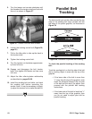
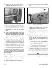
7. Tighten the two cap screws shown in Figure
40.
8. Replace and track the belt with the tracking
knob, so the side of the belt that is tracking
higher (if it is) is even with the top of the
graphite.
— If the lower side of the belt is less than
1
⁄8"
away from the top of the graphite, then
you do not need to make further adjust-
ments for parallel tracking.
— If the lower side of the belt is still more
than
1
⁄8" away from the top of the graphite,
estimate how much the belt moved from
when you originally checked it. Compare
this movement with how much you turned
the two setscrews in step 6, and then
repeat steps 4-7, but adjust the
setscrews discussed in step 6 the
amount that you estimate will fix the par-
allel tracking. Repeat as necessary until
the parallel tracking is correct.
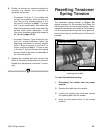
Figure 39. Table removed w/attached supports.
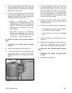
Figure 40. Idler roller adjustment screws.
To adjust the parallel tracking of the sanding
belt:
1. Disconnect the sander from the power
source!
2. Remove the dust port.
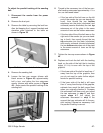
3. Remove the table by removing the lock han-
dles, but keeping the L support brackets and
elevation plate attached to the table as
shown in Figure 39.
4. Remove the sanding belt.
5. Loosen the two cap screws (shown with
black arrows in Figure 40) approximately
half a turn, and notice the four setscrews
nearby (shown with white arrows in Figure
40)—these control the parallel tracking of the
sanding belt.