-8-
G0554 Gear-Head Floor Lathe
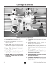
Carriage Controls
A. Compound Rest: Adjustable to 120°.
B. Compound Handwheel:
Graduated to
0.001" or 0.02 mm.
C. Cross Slide: M
oves back-and-forth along
the Y-axis and supports the compound rest.
D. Cross Slide Handwheel: Graduated to
0.001" or 0.02 mm.
E. Saddle: Ri
des on top of the bed ways while
supporting the cross slid
e and apron.
F. Carriage Lock: L
ocks the carriage assem-
bly in place for greater rigidity and accuracy
when cutting.
G. Thread Dial: Used in conjunction with thread
cutting.
H. Thread Dial Chart: Keys for inputting the
d
esired angle of the saw blade.
I. Half Nut Lever: Engages the half nut for
longitudinal power feed and threading opera-
t
ions.
J. Spindle ON/OFF Le
ver: Lifting up turns the
spindle ON clockwise. Push down for coun-
t
erclockwise spindle rotation.
K. Power Feed Lever: Determines longitudinal
a
nd cross feed directions.
L. Longitudinal Handwheel. Manually moves
the carriage in the X-axis. G
raduated to
0.005" or 0.1 mm.
Figure 3. Model G0554 Carriage controls.
A
L
B
F
C
E
D
G
H
I
K
J


