


-34-
G0554 Gear-Head Floor Lathe
Manual Feed
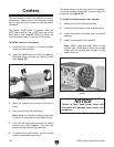
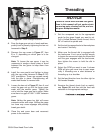
You can manually move the cutting tool around
the lathe by three methods. This section will
review the individual controls on the carriage and
provide descriptions of their uses (see Figure
47).
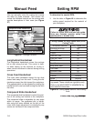
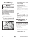
Figure 47. Carriage Controls.
Cross Feed Handwheel
Longitudinal Handwheel
Compound Slide Handwheel
Longitudinal Handwheel
The longitudinal handwheel moves the carriage
left or right along the bed. This control is help-
f
ul when setting up the machine for turning or
when manual movement is desired during turning
operations.
Cross Feed Handwheel
The cross slide handwheel moves the top slide
toward and away from the work. Turning the dial
clockwise moves the slide toward the workpiece.
The graduated dial can be adjusted by holding the
handwheel with one hand and turning the dial with
the other.
Compound Slide Handwheel
The compound slide handwheel controls the posi-
tion of the cutting tool relative to the workpiece.
The compound slide is adjustable for any angle
within its range. The graduated dial is adjust-
a
ble using the same method as the dial on the
cross slide. Angle adjustment is controlled by cap
screws on the base of the compound slide.
Setting RPM
To determine the needed RPM:
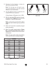
1. Use the table in Figure 48 to determine the
cutting
speed required for the material of
your workpiece.
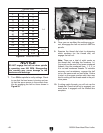
Cutting Speeds for High Speed Steel (HSS)
Cutting Tools
Workpiece Material Cutting Speed (sfm)
Aluminum & Alloys 300
Brass & Bronze 150
Copper 100
Cast Iron, Soft 80
Cast Iron, Hard 50
Mild Steel 90
Cast Steel 80
Alloy Steel, hard 40
Tool Steel 50
Stainless Steel 60
Titanium 50
Plastics 300-800
Wood 300-500
Note: For carbide cutting tools, double the cut-
ting speed. These values are a guideline only.
Refer to the MACHINERY'S HANDBOOK for
more detailed information.
Figure 48. Cutting speed table for HSS cutting
tools.
Failure to follow RPM and feed rate guide-
lines may
threaten operator safety from
ejected parts or broken tools.