


-40-
G0554 Gear-Head Floor Lathe
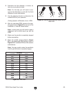
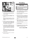
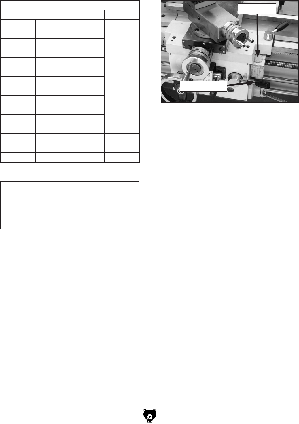
7. Turn ON the spindle to verify settings. Check
to see that the lead screw is turning and ver-
ify
that the apron moves in the correct direc-
tion
by engaging the half nut lever shown in
Figure 59.
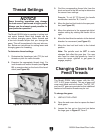
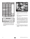
Figure 58. Thread
dial chart.
Figure 59. Half nut and thread dial locations.
Thread Dial
Half Nut Lever
THREAD DIAL
T.P.I DIAL
4 5 6
1-4
7 8 9
10 11 12
13 14 16
18 20 22
23 24 26
28 32 36
40 44 46
48 52 56
64 72 80
88 92 96
104 112
4-1/2 5-1/2
1
or 3
6-1/2 1-1/2
5-3/4 1
8. Once you are confident the settings are cor-
rect, disengage the half nut and turn OFF the
spindle.
9. Examine
the thread dial chart to determine
which numbers (on the thread dial) will
engage the half nut.
Note: There
are a total of eight marks on
the thread dial, including the numbers 1-4.
Any mark can be used to cut even numbered
threads. Use the numbered lines, 1, 2, 3, or
4 to cut odd numbered threads. To maintain
accuracy and consistency, engage the half
nut on the same mark on each pass. Failure
to start on the same number each time may
lead to cutting off the thread made in the pre-
vious
pass.
10. If cutting metric threads, you will not use the
thread
dial. Once the half nut is engaged, you
must leave it engaged until the threads are
complete.
NOTICE
DO NOT engage the half nut when spindle
is operating over 200 RPM. Disregarding
this warning may cause damage to the
leadscrew and bearings.