


-28-
Model G0740 (Mfg. Since 11/12)
— When operating correctly, the machine
runs smoothly with little or no vibration or
rubbing noises.
— Investigate and correct strange or unusual
noises or vibrations before operating the
machine further. Always disconnect the
machine from power when investigating or
correcting potential problems.
10. With the spindle lever in the down position, the
spindle should be rotating counterclockwise—
down and toward you as you face the lathe.
— If the spindle and chuck are not rotating
counterclockwise, the power supply
is connected out-of-phase. Stop the
machine, disconnect it from power, then
follow the instructions in the Correcting
Phase Polarity section on Page 17. After
correcting the wiring, repeat Steps 7–10.
11. Press the STOP button to turn the lathe OFF,
then, without resetting the STOP button, try
to restart spindle rotation. The spindle should
not start.
— If spindle rotation does start with the STOP
button pressed in, the STOP button safety is
not operating correctly. This safety feature
must operate properly before continuing
operation. Use the spindle lever to stop the
lathe, disconnect it from power, and call
Tech Support for help.
12. Move the spindle lever to the OFF (middle)
position, reset the STOP button by twisting
it clockwise until it pops out, then restart
spindle rotation.
13. Push the foot brake. The spindle should
come to a quick stop.
— If the brake pedal has no effect on the
lathe, push the STOP button, and refer to
Brake & Switch on Page 80 to make any
required adjustments.
14. Move the spindle lever to the OFF (middle)
position. Remove the end gear cover from
the left side of the headstock. This activates a
safety switch that should prevent the spindle
from starting while this cover is removed.
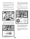
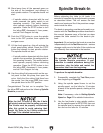
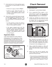
9. Verify that the machine is operating correctly
by pulling the spindle lever out and moving
it down to start spindle rotation (see Figure
29).
Figure 29. Spindle lever in down (forward)
position.
Spindle
Lever
8. Reset the STOP button by twisting it clock-
wise until it pops out. The power lamp on the
control panel should illuminate.
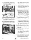
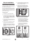
Figure 28. Disengaging carriage components.
Cross Slide
Disengaged
Feed Selection
Lever
Carriage
Engaged
Halfnut
Lever
Disengaged
Half Nut
Lever
Feed
Selection
Lever
7. To ensure the carriage components do not
unexpectedly move during the following
steps, disengage the half nut lever and feed
selection lever (see Figure 28).