


-50-
Model G0740 (Mfg. Since 11/12)
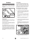
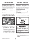
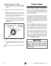
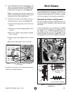
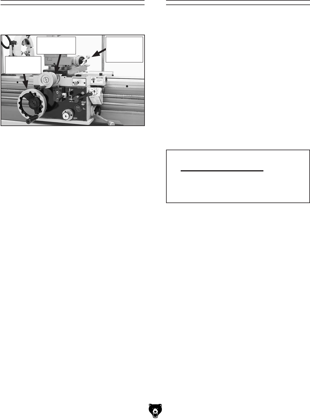
The handwheels shown in Figure 67 allow the
operator to manually move the cutting tool.
Carriage Handwheel
The carriage handwheel moves the carriage left
or right along the bed. It has a graduated dial with
0.01" increments, and one full revolution moves
the carriage 0.80".
Cross Slide Handwheel
The cross slide handwheel moves the tool toward
and away from the work. Adjust the position of the
graduated scale by holding the handwheel with
one hand and turning the dial with the other. The
cross slide handwheel has a direct-read graduat-
ed dial, which shows the total amount of material
removed from the diameter of the workpiece. The
dial has 0.001" (0.02mm) increments, and one
full revolution moves the slide 0.200" (5.08mm).
Rotate the dial collar 180° to read in metric units.
Compound Rest Handwheel
The compound rest handwheel moves the cutting
tool linearly along the set angle of the compound
rest. The compound rest angle is set by hand-
rotating it and securing in place with two hex nuts.
The compound rest has an indirect-read gradu-
ated dial with 0.001" (0.02mm) increments. One
full revolution of the handwheel moves the slide
0.100" (2.54mm). Rotate the dial collar 180° to
read in metric units.
Spindle SpeedManual Feed
Using the correct spindle speed is important for
safe and satisfactory results, as well as maximiz-
ing tool life.
To set the spindle speed for your operation, you
will need to: 1) Determine the best spindle speed
for the cutting task, and 2) configure the lathe con-
trols to produce the required spindle speed.
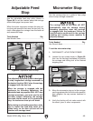
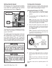
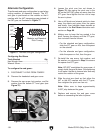
Determining Spindle Speed
Many variables affect the optimum spindle speed
to use for any given operation, but the two most
important are the recommended cutting speed
for the workpiece material and the diameter of
the workpiece, as noted in the formula shown in
Figure 68.
Cutting speed, typically defined in feet per minute
(FPM), is the speed at which the edge of a tool
moves across the material surface.
A recommended cutting speed is an ideal speed
for cutting a type of material in order to produce
the desired finish and optimize tool life.
The books Machinery’s Handbook or Machine
Shop Practice, and some internet sites, pro-
vide excellent recommendations for which cutting
speeds to use when calculating the spindle speed.
These sources also provide a wealth of additional
information about the variables that affect cutting
speed and they are a good educational resource.
Also, there are a large number of easy-to-use
spindle speed calculators that can be found on
the internet. These sources will help you take into
account the applicable variables in order to deter-
mine the best spindle speed for the operation.
Cutting Speed (FPM) x 12
*Recommended
Dia. of Cut (in inches) x 3.14
Spindle
Speed
(RPM)
*Double if using carbide cutting tool
=
Figure 68. Spindle speed formula for lathes.
Figure 67. Carriage Controls.
Carriage
Handwheel
Cross Slide
Handwheel
Compound
Rest
Handwheel