


Model G0746/G0749 (Mfg. Since 3/13)
-51-
Spindle Speed
Using the correct spindle speed is important for
getting safe and satisfactory results, as well as
maximizing tool life.
To set the spindle speed for your operation, you
will need to: 1) Determine the best spindle speed
for the cutting task, and 2) configure the lathe
controls to produce the required spindle speed.
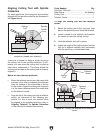
Determining Spindle Speed
Many variables affect the optimum spindle speed
to use for any given operation, but the two most
important are the recommended cutting speed
for the workpiece material and the diameter of
the workpiece, as noted in the formula shown in
Figure 70.
Cutting speed, typically defined in feet per minute
(FPM), is the speed at which the edge of a tool
moves across the material surface.
A recommended cutting speed is an ideal speed
for cutting a type of material in order to produce
the desired finish and optimize tool life.
The books Machinery’s Handbook or Machine
Shop Practice, and some internet sites, pro-
vide excellent recommendations for which cutting
speeds to use when calculating the spindle speed.
These sources also provide a wealth of additional
information about the variables that affect cutting
speed and they are a good educational resource.
Also, there are a large number of easy-to-use
spindle speed calculators that can be found on
the internet. These sources will help you take into
account the applicable variables in order to deter-
mine the best spindle speed for the operation.
Cutting Speed (FPM) x 12
*Recommended
Dia. of Cut (in inches) x 3.14
Spindle
Speed
(RPM)
*Double if using carbide cutting tool
=
Figure 70. Spindle speed formula for lathes.
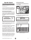
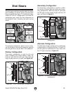
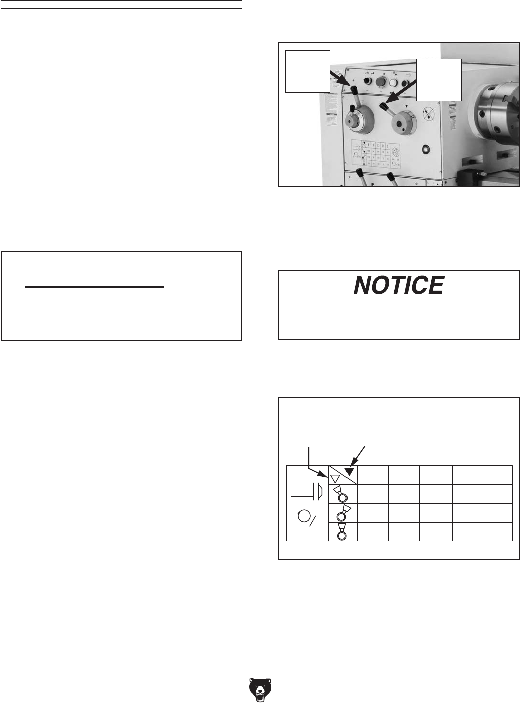
Setting Spindle Speed
The spindle range lever and spindle speed lever,
shown in Figure 71, are used to select one of the
15 spindle speeds.
The spindle speed and range levers control the
gear configuration in the headstock to produce
the selected spindle speed.
Figure 71. Spindle range and speed levers.
To avoid damaging gears, ALWAYS make
sure the spindle is completely stopped
BEFORE moving the spindle speed levers.
The chart below shows the various combinations
of lever positions for achieving a desired speed.
Figure 72. Spindle speed chart and applicable
spindle lever positions.
A B C D E
290845 130 55
75 33
24
175395
240 105 455451600
1150
X
min
Spindle
Range
Lever
Spindle
Speed
Lever
Spindle
Range
Lever
Spindle
Speed
Lever