


Model G0765 (Mfd. Since 5/15)
-41-
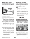
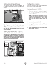
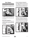
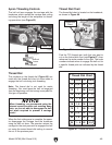
The end gears must be correctly setup for power
feed and threading. Use the photo below to
identify the A, B, C, and D change gears, which
are also referenced on the headstock feed rate
gear chart.
End Gears
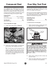
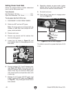
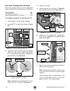
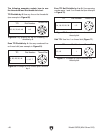
Primary Threading Configuration
This threading configuration is used for inch and
metric threading. Mesh the A, B, and D gears, as
shown in Figure 56. The C gear does not mesh
with any other gears in this configuration, so it is
not important which gear is installed in the C posi-
tion. The B and C gears share a keyed bushing.
Figure 56. Primary threading configuration.
A (20T)
B (80T)
D (80T)
C (20T)
A
B
C
D
B
A
C
D
B
Gear
A
Gear
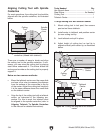
Secondary Threading Configuration
This threading configuration is used for a different
range of threads and feed rates than the primary
threading configuration. Mesh the A and B gears,
and mesh the C and D gears, as shown in Figure
57. The B and C gears share a keyed bushing.
Figure 57. Secondary threading configuration.
A (20T)
B (80T)
D (80T)
C (20T)
A
B
C
D
B
A
C
D
C
Gear
B
Gear
A
Gear
C
Gear
D
Gear
D
Gear
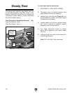
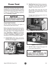
Power Feed Configuration
The end gears are preset by the factory in this
configuration, which is only used for power feed-
ing. Mesh the top 20T A gear with the 80T B gear,
and mesh the 20T C gear with the 80T D gear
(see Figure 55).
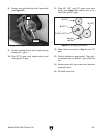
The following subsections explain how to config-
ure the end gears, which are accessed by remov-
ing the end cover.
Figure 55. Power feed end gear configuration.
A (20T)
B (80T)
D (80T)
C (20T)
A
B
C
D
B
A
C
D
D Gear
(80T)
A Gear
(20T)
B Gear
(80T)
C
B
Figure 54. Change gear identification.
A
D
C Gear
(20T)