


-54-
Model G0765 (Mfd. Since 5/15)
Backlash Adjustment
Backlash is the amount of free play felt while
changing rotation directions with the handwheel.
This can be adjusted on the cross slide leadscrew.
Before beginning any adjustment, make sure all
associated components are cleaned and lubri-
cated and locks are loose.
When adjusting backlash, tighten the components
enough to remove backlash, but not so much that
the components bind the leadscrew, making it
hard to turn. Overtightening will cause excessive
wear to the sliding block and leadscrew.
Reducing backlash to less than 0.002" is
impractical and can lead to accelerated wear
in the leadscrew and other components.
Avoid the temptation to overtighten the
backlash nut or screw while adjusting.
Cross Slide
Tools Needed: Qty
Hex Wrench 2.5mm ........................................... 1
Hex Wrench 3mm ............................................. 1
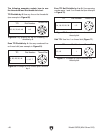
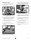
The cross slide backlash is adjusted by tighten-
ing and loosening the inner and outer cap screws
shown in Figure 80. The inner screw adjusts
the height of the leadscrew nut, taking up lash
between the nut and leadscrew.
Angle the compound rest so you can access
the cap screws shown in Figure 80. Loosen the
outer cap screws, adjust the inner cap screw,
then tighten the outer cap screws. Move the
cross slide handwheel back and forth and adjust
backlash until it is approximately 0.002"–0.003",
as indicated on the graduated dial. Re-adjust the
compound rest angle when you are finished.
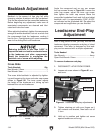
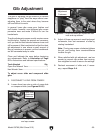
Figure 80. Cross slide backlash adjustment cap
screw.
Outer Cap
Screws
Inner Cap
Screw
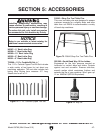
Leadscrew End-Play
Adjustment
After a long period of time, you may find that the
leadscrew develops excessive end-play or lateral
movement. This lathe is designed so that end-
play can be removed with a simple adjustment.
Tools Needed Qty
Hex Wrench ................................................. 4mm
Open-End Wrench 12mm .................................. 1
To remove leadscrew end play:
1. DISCONNECT LATHE FROM POWER.
2. Loosen set screw shown in Figure 81 sev-
eral turns.
3. Tighten retaining nut with your fingers so it
just contacts end bracket, then back nut off
1
⁄8 turn.
4. Hold nut in position and tighten set screw
against leadscrew until snug.
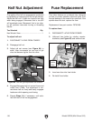
Figure 81. Leadscrew end-play adjustments.
Retaining Nut
Leadscrew
End Bracket
Set Screw