


-42-
Model G0765 (Mfd. Since 5/15)
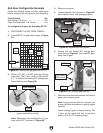
End Gear Configuration Example
Follow the example below to better understand
how to configure the end gears for inch threading.
Tools Needed Qty
Hex Wrench 4 & 5mm ..................................1 Ea
Open-End Wrenches 13 & 14mm .................1 Ea
To configure end gears for threading 20 TPI:
1. DISCONNECT LATHE FROM POWER!
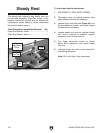
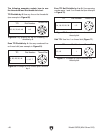
2. Locate 20 TPI on gear chart shown in Figure
58.
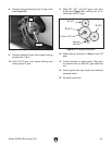
4. Remove end cover.
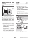
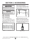
5. Loosen adjuster hex nut shown in Figure 60,
pivot adjuster down, and disengage gears.
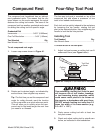
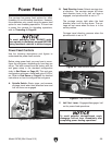
3. Gather 40T, 65T, and 50T gears per change
gear chart. The C gear, which is indicated by
a "/", is installed on existing B/C change gear
keyed bushing (see Figure 59).
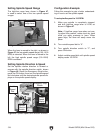
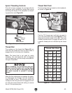
Figure 58. Locating change gears for 20 TPI.
TPI Scale TPI Scale
Thread Dial Chart
12
13
14
16
18
19
20
22
24
1,3,5,7
1
1,5
1 – 8
1,5
1
1,3,5,7
1,5
1 – 8
26
28
32
36
38
40
44
48
52
1,5
1,3,5,7
1 – 8
1,3,5,7
1,5
1 – 8
1,3,5,7
1 – 8
1,3,5,7
TPI Gear Setup TPI Gear Setup
12
13
14
16
18
19
20
22
24
A B C D A B C D
40 30 26 40 60 65
40 30
35
40
45
57
50
55
60 60
40
40
40
40
40
40
40
50
65 65
65 65
65 65
65
65
65 65
65 65
65
65
60
60
28
32
36
38
40
44
48
52
20
20
20
20
20
20
20
20
50 60
35
40
45
57
50
55
60
65
C
Gear
40T
Gear
65T
Gear
50T
Gear
20 TPI
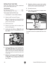
Figure 59. B/C change gear and keyed bushing
(gears removed for clarity).
C Gear
B Gear
Keyed Bushing
Front Back
Note: Depending upon configuration, C gear
may not be 20T, as shown in Figure 59.
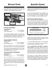
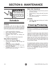
6. Loosen hex nut behind B/C change gear
shaft shown in Figure 61, then slide B/C gear
away from D gear.
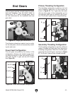
Figure 60. Adjuster hex nut location.
Adjuster
Hex Nut
A Gear
B Gear
C Gear
D Gear
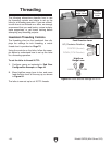
7. Remove cap screws and washers that secure
gears, then remove gears.
Note: If any gears are difficult to remove, use
a large flat head screwdriver to gently wiggle
them off.
Leave existing C gear on keyed bushing. The
C gear will not mesh with any of the other
gears in this 20 TPI threading setup.
Figure 61. B/C change gear hex nut.
Hex Nut
D Gear
B/C Gear
Cap Screws
& Washers