


-18-
Model G0766 (Mfd. Since 07/15)
4. If bolting lathe to floor, skip to Step 7.
Otherwise, move tailstock, tool rest assem-
bly, and headstock to one end of lathe bed
way (refer to Operations, beginning on Page
2020).
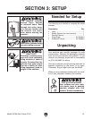
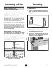
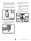
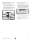
5. Use assistants to lift one end of lathe onto
support blocks and stabilize lathe in prepara-
tion for installing machine feet (see Figure
13).
Figure 13. Legs supported for feet installation.
Support Block
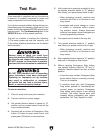
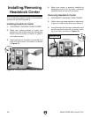
6. Remove top hex nut from feet, insert feet in
mounting holes in leg (see Figure 14), then
thread top hex nut back on. Do not tighten
hex nuts yet. Remove supporting block and
repeat Steps 5–6 on other leg.
Figure 14. Machine feet installed.
7. Place level on lathe bed and make necessary
adjustments so bed is level from side-to-side
and front-to-back.
— If you are using machine feet, adjust top
and bottom hex nuts on each leg to level
bed; then tighten hex nuts to secure these
adjustments.
— If you are bolting lathe to floor, use shims
under legs to level bed; then tighten
mounting fasteners.
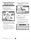
8. Insert tool rest into tool rest base and tighten
tool rest lock lever, as shown in Figure 15.
Figure 15. Tool rest installed on the tool rest
base.
Tool Rest
Tool Rest
Lock Lever
Tool Rest Base