Model G0766 (Mfd. Since 07/15)
-23-
To position tool rest forward/backward and
along the length of the bed:
1. Loosen tool rest base lock lever and move
tool rest assembly to desired position on
lathe bed, as shown in Figure 18.
Note: To maximize support, the tool rest
base should always be locked on both sides
of the bed. Never pull the tool rest so far back
that it is only secured on one side.
2. Re-tighten tool rest base lock lever to secure
tool rest assembly in position.
Note: The large clamping hex nut under-
neath the tool rest base will require occa-
sional adjusting to ensure proper clamping
pressure of the tool rest assembly to the bed.
Turn this hex nut in small increments to fine
tune the clamping pressure as needed.
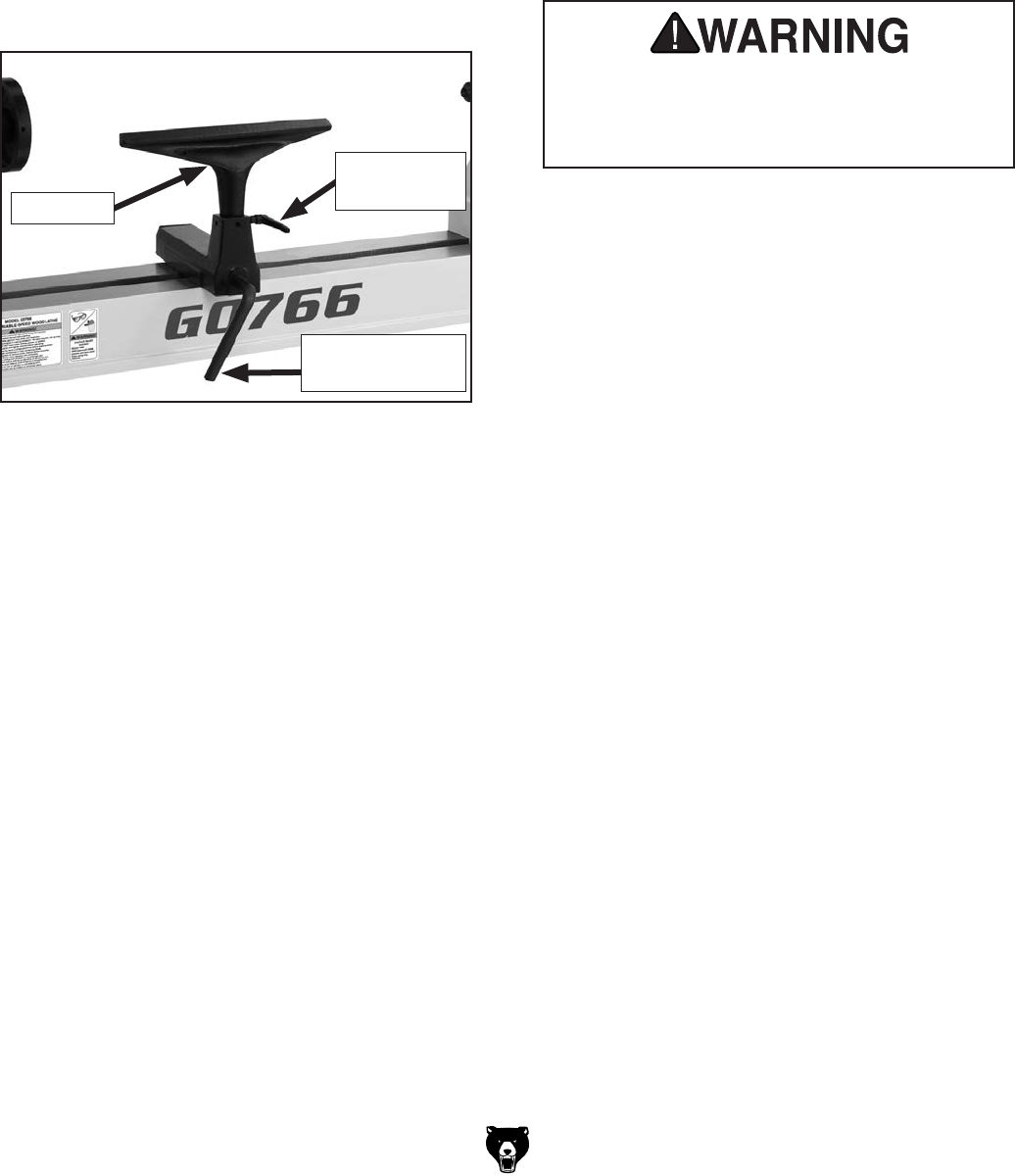
Figure 18. Tool rest controls.
Tool Rest
Tool Rest
Lock Handle
Tool Rest Base
Lock Lever
To adjust angle or height of tool rest:
1. Loosen tool rest lock handle (see Figure 18).
2. Position tool rest in desired location.
3. Re-tighten tool rest lock handle to secure tool
rest in position.
Always operate lathe with tool rest assem-
bly firmly locked in position. Otherwise,
serious personal injury may occur by tool
being pulled from operator's hands.


