


-26-
Model G0766 (Mfd. Since 07/15)
Headstock Faceplate
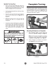
Installing Faceplate
To prevent faceplate and workpiece sepa-
rating from spindle during operation, head-
stock faceplate MUST be firmly threaded
onto spindle and secured in place by fully
tightening the two faceplate set screws.
If these instructions are not properly per-
formed, serious personal injury could occur.
Note: To remove faceplate, disconnect lathe from
power source and perform steps above in reverse.
To install faceplate:
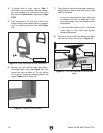
1. DISCONNECT MACHINE FROM POWER!
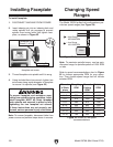
2. Insert indexing pin into an indexing hole and
rotate spindle until pin engages to prevent
spindle from turning while you tighten face-
plate, as shown in Figure 23.
3. Thread faceplate onto spindle until it is snug.
4. Using included 4mm hex wrench, tighten two
set screws along inside diameter of faceplate
to secure it to spindle (see Figure 23).
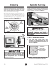
Changing Speed
Ranges
The Model G0766 pulley belt configurations pro-
vide two speed ranges (see Figure 24).
Note: To maximize spindle torque, use low spin-
dle speed range for spindle speeds of 1200 RPM
or less.
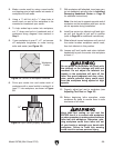
Refer to speed recommendations chart in Figure
25 to choose appropriate RPM for your opera-
tion. Then choose speed range that will include
selected RPM.
Changing Speed Ranges
Diameter
of Work-
piece
Roughing
RPM
General
Cutting
RPM
Finishing
RPM
Under 2" 1520 3200 3200
2–4" 760 1600 2480
4–6" 510 1080 1650
6–8" 380 810 1240
8–10" 300 650 1000
10–12" 255 540 830
12–14" 220 460 710
14–16" 190 400 620
Figure 25. Model G0766 speed
recommendations.
Figure 24. Speed range belt positions.
Spindle
Motor
B
A
A = High Range
330-3200 RPM
B
= Low Range
100-1200 RPM
Figure 23. Locking spindle with indexing pin and
faceplate set screw.
Faceplate Set
Screw (1 of 2)
Indexing Pin