


-18-
Model G7943/G7944 (Mfg. 10/02+)
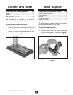
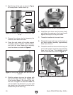
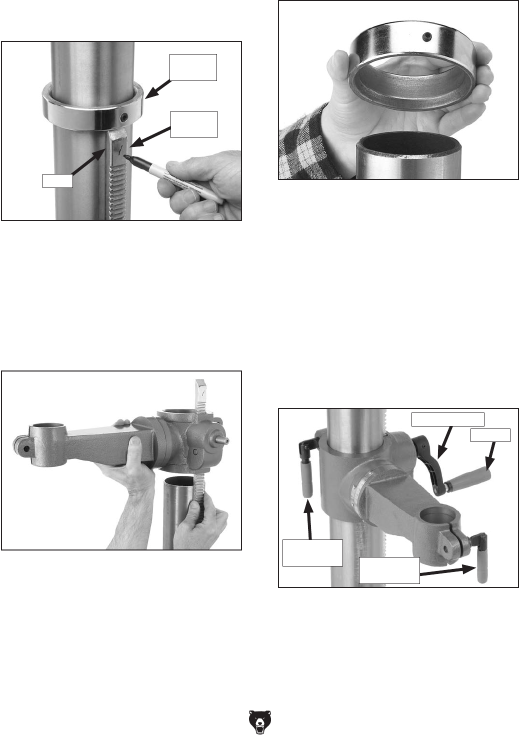
3. Remove the column ring by loosening the
setscrew, and remove the rack.
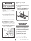
4. Place the rack inside of the table support
assembly, mesh it together with the pinion,
and slide the table support/rack assembly
over the column, as shown in Figure 9.
Figure 9. Sliding table support and rack over the
column.
5. Slide the column ring over the column with
the beveled edge facing down (Figure 10),
fit the beveled edge of the column ring over
the rack, and tighten the setscrew. Note: Do
not over-tighten the setscrew or you may split
the column ring. Also make sure the rack is
seated firmly in the lower ring.
Figure 10. Correct column ring orientation.
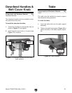
6. Install the crank lever over the pinion shaft,
and tighten the setscrew in the crank handle
against the flat part of the pinion shaft.
7. Thread the handle into the crank lever.
8. Thread the large lock lever into the back of
the table support assembly approximately
three turns, for now.
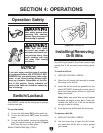
9. Thread the small lock lever into the front part
of the table support assembly approximately
three turns, for now. The assembly should
now be assembled as shown in Figure 11.
Figure 11. Handles and lock levers installed.
Large Lock
Lever
Crank Lever
Handle
Small Lock
Lever
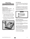
2. Mark the top of the rack, as shown in Figure
8, to keep track of which end is up.
Figure 8. Marking top of rack to show which end
is up.
Column
Ring
Marking
Location
Rack