


-16-
G1010 4" x 6" Metal-Cutting Bandsaw
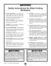
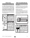
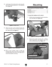
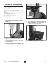
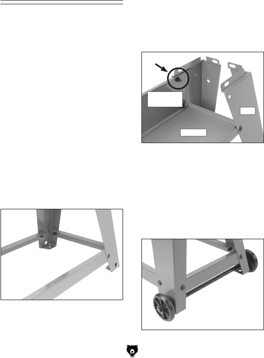
Figure 6. Upper stand support and tool tray.
2. Secure the upper stand support to the inside
of the legs using the carriage bolts. Start by
securing the upper carriage bolt highlighted
in Figure 6.
3. Attach the tool tray to the legs as shown in
Figure 6. One side of the tool tray will share
the lower carriage bolt of the upper stand
support.
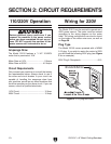
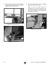
4. Slide the axle through the two holes at the
bottom of the legs as shown in
Figure 7.
5. Slide the wheels onto the axle with two
5
⁄8"
flat washers on either side of the wheel
.
6. With a pair of pliers, insert a cotter pin
through each hole at the end of the axle and
bend back one end of the cotter pin to keep
the wheel in place.
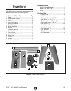
Stand Assembly
Components and Hardware Needed: Qty
Carriage Bolts
5
⁄16"-18 x
3
⁄4" ............................... 14
Hex Nuts
5
⁄16-18 ................................................14
Flat Washers
5
⁄16" ..............................................14
Legs ....................................................................
4
Long Leg Braces ................................................
2
Short Leg Braces ...............................................
2
Upper Stand Support .........................................
1
Tool Tray .............................................................
1
Axle ....................................................................
1
Wheels ................................................................
2
Cotter Pins ..........................................................
4
Transport Handle ................................................
1
Rubber Feet ........................................................
2
Flat Washers
3
⁄8" .................................................4
Hex Nuts
3
⁄8"-16 ..................................................4
Flat Washers
5
⁄8" .................................................4
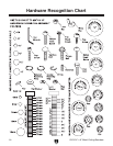
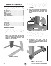
To assemble the stand:
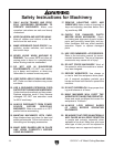
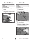
1. Attach the short leg braces and then the long
leg braces to the legs with carriage bolts,
washers and hex nuts as shown in
Figure
5.
Note: At this time, tighten with a 12mm
wrench or socket just enough to secure the
parts. F
inal tightening will take place when
the stand is fully assemble
d.
Figure 5. Leg braces.
Figure 7. Axle and wheels.
Tool Tray
Upper Stand
Support
Leg