


-26-
G1021X 15" Extreme Series Planer
Table Parallelism Inspection
Use your Rotacator to inspect the table parallel-
ism. If you do not have a Rotacator, a wood block
and feeler gauges may be used, but extra care
must be taken to ensure accuracy.
If the table is
not within the maximum allowable tolerances, it
must be adjusted.
Table Parallelism Adjustments
The table is adjusted by turning the chain sprock-
ets underneath the table for movements over
0.016" or by adjusting how the table is mounted
on the columns for movements under 0.016".
To adjust the table parallelism:
1. DISCONNECT THE PLANER FROM THE
POWER SOURCE!
2. Remove the cabinet panel and locate the
chain on the underside of the table.
3. Loosen the idler sprocket (see Chain Tension
instructions on
Page 25).
4. Move the chain away from only the sprocket
you want to adjust so only that sprocket can
be turned independent of the chain
.
Note: If the left side of the table is too high,
the left two sprockets will need to be adjusted.
Each tooth on the sprocket represents .016"
of vertical movement as the cogs are turned.
Make sure, as you turn the sprockets, to keep
an accurate tooth count to ensure that the
table is adjusted equally.
5. Mark the location of one tooth in the sprocket
that you are adjusting.
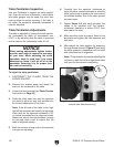
NOTICE
When making adjustments, tighten fasten-
ers after each step to ensure the accuracy
of your tests. When adjusting the chain
sprockets, keep in mind that if the chain
becomes too loose, it will fall off of all the
sprockets. Returning it to its proper loca-
tion can be frustrating.
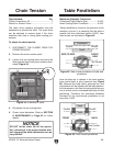
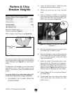
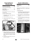
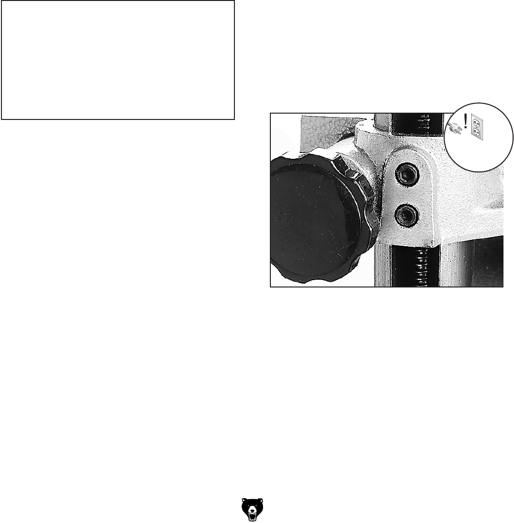
Figure 27. Close up of table micro-adjustment
screws (one side shown only).
6. Carefully turn the sprocket (clockwise to
lower the table; counterclockwise to raise the
table) just enough to position the next tooth at
the marked location, then fit the chain around
sprocket again.
7. Repeat Steps 4–6 with each sprocket that
needs to be adjusted until the table-to-
cutterhead clearance is within 0.016" from
one side to the other.
8. Make sure the chain is properly fitted on the
sprockets and tighten the idler sprocket and
lock bolts.
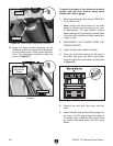
9. Micro-adjust the table position by loosening
the cap screws shown in
Figure 27 and lifting
the table upward or downward until the table
and cutterhead are in alignment.
Note: This process may require adjusting the
columns on both the left and right hand sides
until you find the correct combination.