


-30-
G1021X 15" Extreme Series Planer
Chip Deflector
Positioning
Chip Deflector Gap Setting Qty
If Planer Used w/Dust Collector ......................
1
⁄4''
If Planer Used w/o Dust Collector ..................
1
⁄16''
Tools Needed: Qty
Wrench or Socket 10mm ...................................
1
Hex Wrench 5mm ..............................................
1
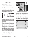
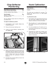
The chip deflector keeps chips from falling onto
the outfeed roller.
To adjust the deflector position:
1. DISCONNECT THE PLANER FROM THE
POWER SOURCE!
2. Remove the dust port and top cover.
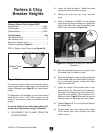
3. Loosen the chip deflector mounting bolts
(see Figure 34).
4. Make sure the deflector is beveled toward the
cutterhead. Move the deflector until the edge
is the correct distance (given above) from the
closest carbide insert. Use the cutterhead
pulley to rotate the cutterhead to ensure
clearance.
5. Re-tighten the mounting bolts and return the
top cover to the planer.
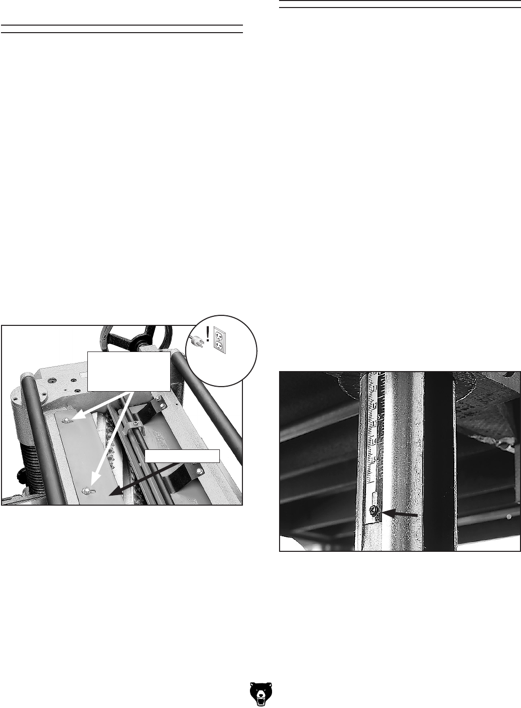
Chip Deflector
Mounting Bolts
(2 of 3 Shown)
Chip Deflector
Figure 34. Chip deflector and mounting bolts.
Tools Needed: Qty
Phillisp Screwdriver ...........................................
1
Calipers .............................................................
1
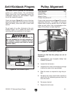
The scale can be adjusted for accuracy. The
machine will need to be run to make proper
adjustments.
To calibrate the scale:
1. Set the table to the approximate thickness of
your test lumber. Measure the lumber with
calipers to determine its exact thickness.
2. Move the table to
1
⁄16'' under the thickness of
your lumber and feed your test board through
the planer.
3. Turn the handwheel one full rotation and run
the board through once more. Turn the board
over and repeat.
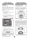
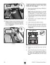
4. Re-measure the board and compare your
results with the scale. If there is a discrep
-
ancy, loosen the screw (see Figure
35) and
adjust as necessary.
Figure 35. Depth scale adjustment screw.
Scale Calibration