


-28-
G1021X 15" Extreme Series Planer
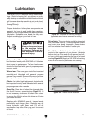
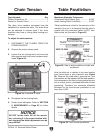
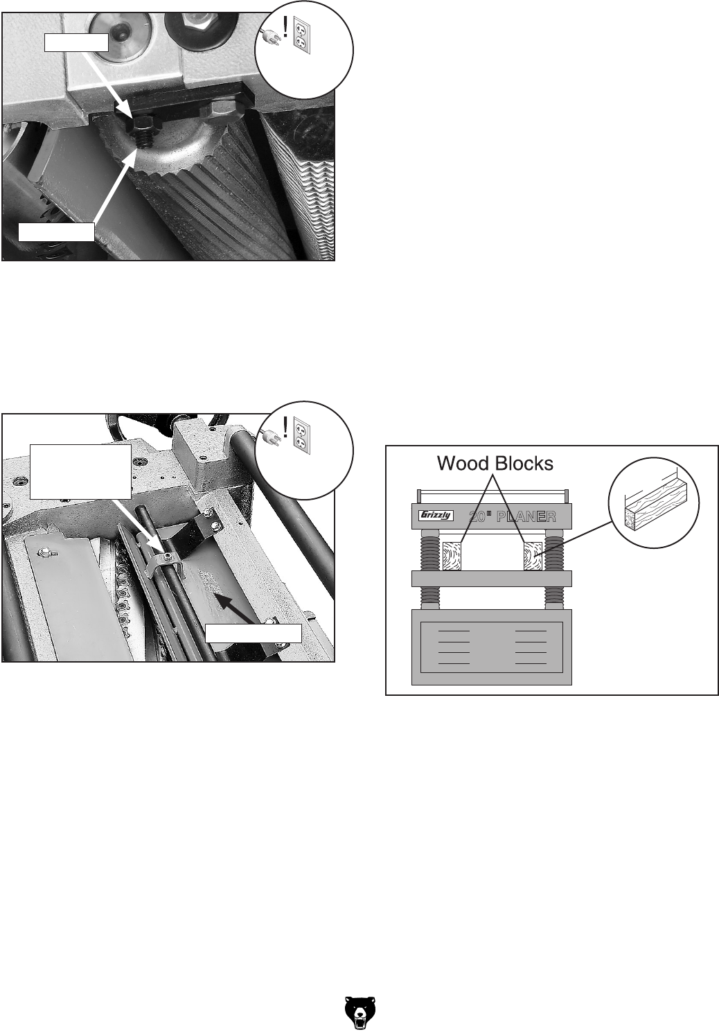
Figure 30. Roller height adjustment controls.
Set Screw
Jam Nut
10. Using the same zeroed reference on the
Rotacator, adjust the height of the chip break
-
er and outfeed roller to their given specifica
-
tions. The adjustment controls for each are
shown in
Figure 31.
To adjust the height of the infeed and outfeed
rollers, and the chip breaker using wood
blocks and a feeler gauge:
1. Make the wood blocks by cutting a STRAIGHT
6' long 2x4 in half.
Note: Having the wood blocks at an even
height is critical to the accuracy of your over
-
all adjustments. For best results, remove
board warpage by squaring the narrow sides
of the 2x4 with a jointer and table saw before
cutting in half.
2. DISCONNECT THE PLANER FROM THE
POWER SOURCE!
3. Lower the bed rollers below the table.
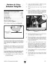
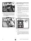
4. Place one wood block along the left side of
the table, and place the other wood block
along the right side of the table, as illustrated
in Figure 32.
Figure 32. Wood blocks on table.
5. Remove the dust port, top cover and belt
cover.
6. Adjust the table and use the feeler gauge until
you have a 0.040" gap between the edge of
a carbide insert at bottom dead center (find
by rocking cutterhead pulley) and the wood
blocks.
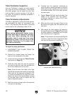
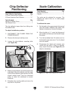
Figure 31. Adjustment locations for the chip
breaker.
Chip Breaker
Chip Breaker
Adjustment
Screw