


G1021X 15" Extreme Series Planer
-27-
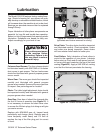
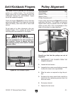
Rollers & Chip
Breaker Heights
Distance Below Cutter Edge at BDC*
Infeed Roller ..............................................
0.040"
Chip Breaker .............................................
0.040"
Outfeed Roller ...........................................
0.040"
Tools Needed: Qty
Hex Wrench 3mm ..............................................
1
Hex Wrench 5mm ..............................................
1
Wrench or Socket 10mm ...................................
1
Rotacator (optional, Page 20
) ........................... 1
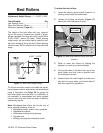
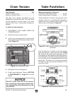
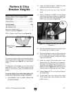
*BDC = Bottom Dead Center (see
Figure 28).
Figure 28. Cutter edge at bottom dead center.
To ensure accurate results and make the adjust-
ment process quicker and easier, we recommend
using a Rotacator
(see Page 20) for these adjust-
ments.
If a Rotacator is not available, a pair of even-sized
wood blocks and a 0.40" feeler gauge can be
used, but care must be taken to achieve accurate
results.
To set the height of the infeed and outfeed roll
-
ers and the chip breaker using a Rotacator:
1. DISCONNECT THE PLANER FROM THE
POWER SOURCE!
2. Lower the table at least 4" below the head
casting and lock the table in place.
3. Remove the dust port, top cover, and belt
cover.
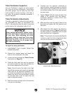
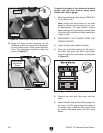
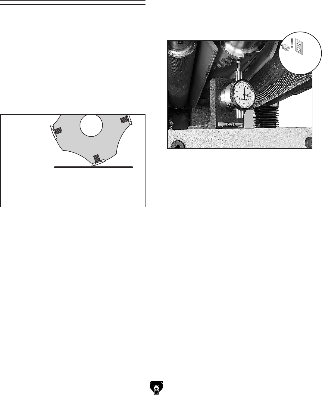
4. Using a Rotacator, find BDC of any carbide
insert edge by slowly rocking the cutterhead
pulley back and forth, and set the Rotacator
dial to zero, as shown in
Figure 29.
5. Move the feed speed knob to neutral to allow
the infeed roller to rotate by hand.
6. Place the Rotacator under the right-hand side
of the infeed roller and find bottom dead cen
-
ter on a serrated edge by rocking the infeed
roller back and forth.
7. Adjust the height of the infeed roller on the
same side as the Rotacator to the specifica
-
tion given at the beginning of this procedure,
using the zero setting of the Rotacator as a
reference point.
Figure 30 shows the jam nut
and set screw for adjusting the roller height.
8. Repeat Steps 6 & 7 on the left-hand side of
the infeed roller.
9. Double-check and micro-adjust both sides
of the infeed roller, then carefully lock both
sides in place.
Figure 29. Example of finding BDC with the
Rotacator.