


G1037 Planer / Moulder -9-
Stand Assembly
SECTION 4: ASSEMBLY
Most of your Planer/Moulder has been assem-
bled at the factory. The few remaining pieces
should go together quickly and easily. With just a
few simple hand tools, completion of your new
Planer/Moulder is quite straight forward.
We have organized the assembly process into
steps. Please follow them in sequence.
Caution: All die-cut metal parts have a sharp
edge (called “flashing”) on them after they are
formed. This is removed at the factory.
Sometimes though, a bit of flashing might escape
inspection. Please examine the edges of all die-
cut metal parts before handling them.
1. Locate the four legs and the long upper and
lower stand braces.
2. The square mounting holes on either side of
the legs are not the same. On one side the
square holes are parallel to the leg, at an
angle on the other. Attach the long upper
and lower braces to the side with the parallel
holes. Use the
5
/16
" - 18 x
5
/8
" Carriage bolts,
5
/16
" - 18 Hex nuts, and
5
/16
" Flat washers pro-
vided. Hand tighten for now. Figure 4.
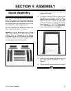
Figure 3. Overview of stand parts.
3. Attach the short upper and lower braces to
the stand panels assembled in step 1.
Figure 3.
4. Tighten down all the stand bolts at this point.
Figure 4.