


G4227 Sliding Table -11-
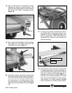
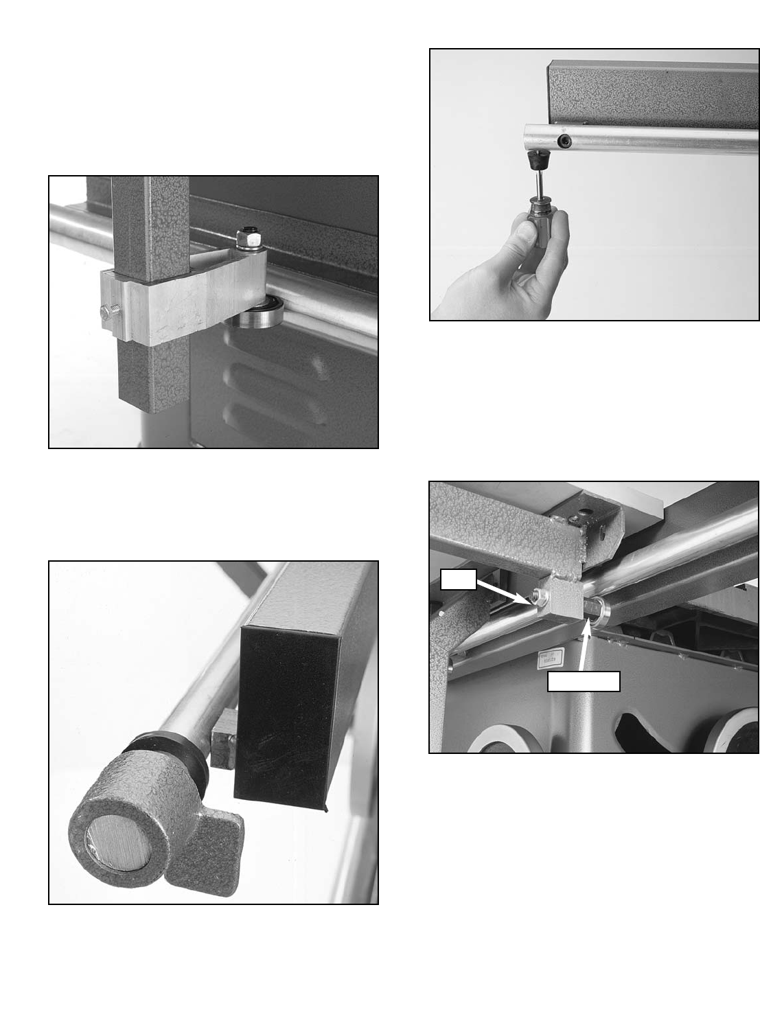
Figure 11. Lower pinch roller adjustment.
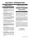
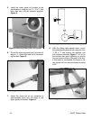
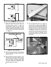
Figure 9. Front stop installation.
10. Slide the rubber ring onto the front rail and
install the front stop assembly. Figure 9.
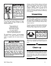
11. Install the rear stop using the #10-24 x
3
⁄4''
Phillip head screw provided. Figure 10.
Figure 10. Rear stop installation.
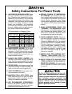
12. Slightly loosen the lower front and rear pinch
roller nuts with a 14mm wrench. Now turn
their eccentric shafts with a 17mm wrench
until they are at their lowest position. Figure
11.
13. Prior to adjusting the upper eccentric
grooved rollers, it must be understood that
the grooved rollers need to remain in full
contact with the upper rail during the adjust-
ment process in order to achieve proper
adjustment. Figure 12.
Nut
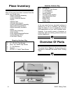
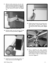
Figure 8. Adjust lower guide bearing.
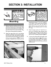
9. Slide the table mechanism onto the rails.
Adjust the lower bearing guide until it is cen-
tered on the lower guide rail as in Figure 8.
Please note: the upper grooved rollers can
be easily derailed at this point (see Figure
12).
Eccentric