


Page 8SKU 47158
For technical questions, please call 1-800-444-3353.
5. Then, secure the Micro Mill/Drill Machine to the workbench, using the four 3/8”
diameter bolts of appropriate length, four lock washers, and four nuts as
mentioned in Step #2.
MACHINE ADJUSTMENT INSTRUCTIONS
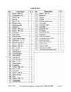
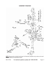
NOTE: For additional references to the parts listed below, refer to the Assembly
Diagram on page 14.
To Use The Adjustment Controls:
1. CAUTION: ALWAYS TURN OFF THE MICRO MILL/DRILL MACHINE, UNPLUG
ITS ELECTRICAL POWER CORD/PLUG (part #128), AND WAIT UNTIL IT
COMPLETELY STOPS RUNNING BEFORE MAKING ANY ADJUSTMENTS.
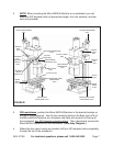
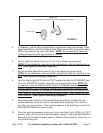
2. To adjust the height of the Spindle Box (part #24) to accommodate the work-
piece being milled/drilled; turn the Lifting Hand Wheel (part #97) clockwise to
raise the Spindle Box, and turn the Lifting Hand Wheel counterclockwise to lower
the Spindle Box. (See Figure B, and Assy. Diagram.)
3. To lower and raise the Chuck (part #132); pull the Handle Shaft (part #87)
down to lower the Chuck. Pull the Handle Shaft up to raise the Chuck.
(See Figure B, and Assy. Diagram.)
4. To adjust the fine feeding mechanism; push in on the Clutch Lever (part #65)
which is located on the Fine Feeding Hand Wheel (part #97). Turn the Fine
Feeding Hand Wheel clockwise to bring the tip of the Chuck (part #132) up. Turn
the Fine Feeding Hand Wheel counterclockwise to bring the tip of the Chuck
down. The Fine Feeding Hand Wheel may be adjusted from 0” to 1-1/4” up or
down. NOTE: For normal, manual feeding, make sure the Clutch Lever is pulled
out. (See Figure B, and Assy. Diagram.)
5. To move the Worktable (part #105)to the front and to the back; turn the
Longitudinal Feed Hand Wheel (part #97) clockwise to position the Worktable
toward the front of the machine. Turn the Longitudinal Feed Hand Wheel
counterclockwise to position the Worktable toward the back of the machine. (See
Figure B, and Assy. Diagram.)
6. To move the Worktable (part #105) to the right and to the left; turn the Cross
Feed Hand Wheel (part #97) clockwise to position the Worktable to the right.
Turn the Cross Feed Hand Wheel counterclockwise to position the Worktable to
the left. (See Figure B, and Assy. Diagram.)