


For technical questions, please call 1-800-444-3353;
Troubleshooting section at end of manual.
Page 14SKU 55167
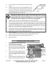
5. Remove the Wire Feed Roller (34) and install one with the proper size (.030”) facing
up.
6. Reassemble the Roller Bracket (44), Screws (45), and Washers (46). Put the welding
wire into the top groove on the Roller, if it is not already in place.
7. Swing the Wire Feed Adjusting Spring (36) down while pressing it forward to latch it
over the Tension Adjusting Screw (37). Tighten the Tension Adjusting Screw until the
Wire Feed Bearing (35) just touches the wire and then three full turns farther.
8. Turn the Nozzle (3) counterclockwise while pulling to remove. Using the third oval hole
on the provided Wrench (43), turn the Contact Tip (2b) counterclockwise and remove
it.
9. Install an appropriately sized Contact Tip (2b, 0.9 mm) over the wire and tighten to the
Torch with the Wrench (43).
10. Test and adjust the drive tension as explained in steps 12-14 on the previous page.
11. Close the welder’s cover and switch the Welder OFF. Unplug the Welder if it is not to
be used at this time.
TRIGGER SWITCH REPLACEMENT
1. WARNING! Turn the welder OFF and unplug it before proceeding.
This procedure should be performed by a qualified technician.
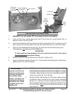
2. Turn the Handle Lock Ring (1d) at the base of the torch handle counterclockwise and
slide it down the cable.
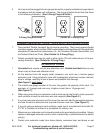
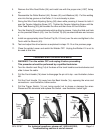
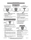
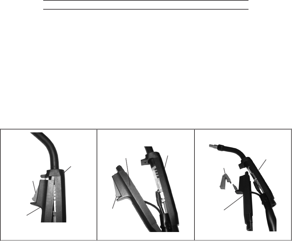
3. Pull the Front Handle (1b) down to disengage the pin at its top - see illustration, below
left.
4. Pull the Front Handle (1b) away from the Back Handle (1a), exposing the wires and
connections - see illustration, below center.
5. Pull the Trigger Switch (1c) out, being careful not to stress or damage the wires.
Disconnect the terminals and replace the Switch - see illustration, below right.
Back
Handle
(1a)
Front
Handle (1b)
Trigger
Switch (1c)
Back
Handle
(1a)
Front
Handle (1b)
Trigger
Switch (1c)
Back
Handle
(1a)
Front
Handle
(1b)
Trigger
Switch
(1c)