


SKU 91146 For technical questions, please call 1-800-444-3353. PAGE 17
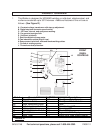
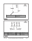
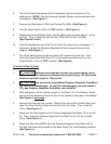
6. Turn the Pressure Adjustment Knob
clockwise
to tighten the tension of the
welding wire. NOTE: Use the Pressure Indicator Scale to set the desired drive
roll pressure. (See Figure I.)
7. Remove the Gas Nozzle (100A) and Contact Tip (90A). (See Figure I.)
8. Turn the Power Switch (10) to its “ON” position. (See Figure I.)
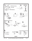
9. Depress the Inching Button (36A) until the welding wire extends about 1” out of
the Gun. Then, reinstall the Gas Nozzle (100A) and Contact Tip (90A).
(See Figures F and I.)
10. Feed the welding wire out of the Gun to check for proper drive roll pressure. If
necessary, tighten the Pressure Adjustment Knob to prevent the wire from
slipping. (See Figure I.)
11. Cut off the welding wire so that only about 3/8” extends from the Gun. Then
close the Upper Right Side Panel (21) of the welding machine and turn the
Power Switch (10) to its “OFF” position. (See Figure I.)
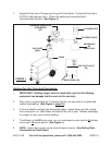
To Install A Gas Cylinder:
1. CAUTION! Using an oversized gas cylinder can cause tipping, result
ing in cylinder and equipment damage and personal injury. Do not exceed
maximum cylinder weight of 100 pounds.
2. CAUTION! Do not use the Argon/Mixed Pressure Regulator/Flow Meter
(43) with CO shielding gas. To use CO shielding gas, you must install a
CO gas Pressure Regulator/Flow Meter (not included).
2
2
2
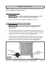
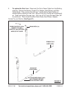
3. With assistance, set the cylinder upright on the Base (19) of the Welder. Make
sure to use the accessory Chain to secure the cylinder to the body of the Welder.
(See Figure J, next page.)
4. Remove the Cap from the cylinder. Stand to the side of the cylinder Valve, and
open the Valve slightly to blow dust and dirt from the Valve. Then, close the
Valve. (See Figure J.)
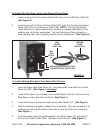
5. Make sure the Flow Adjust on the Pressure Regulator/Flow Meter (43) is turned
off. Then, screw the Pressure Regulator/Flow Meter firmly onto the cylinder
Valve. (See Figure J.)
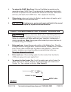
6. Attach the Gas Hose (202A) from the Pressure Regulator/Flow Meter (43) to
the Gas Inlet Valve (29) located on the Back Panel (30) of the Welding machine.
(See Figure J.)